Example for Configuring DR Election Through OSPFv3
Networking Requirements
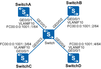
In Figure 1, SwitchD uses the default priority 1. Switch must be elected as the DR. SwitchC must be elected as the BDR. SwitchB cannot become the DR.
Configuration Roadmap
The configuration roadmap is as follows:
Configure IPv6 addresses for interfaces.
Configure a router ID for each switch, enable OSPFv3, and specify the network segments.
Check the DR and BDR status of each switch when the default priority is used.
Set a DR priority for the interface on each switch and check whether the switch has become the DR or BDR.
Procedure
- Add interfaces to VLANs.
# Configure SwitchA. Ensure that the configurations of Switch, SwitchB, SwitchC, and SwitchD are the same as that of SwitchA.
<HUAWEI> system-view
[HUAWEI] sysname SwitchA
[SwitchA] vlan 10
[SwitchA-vlan10] quit
[SwitchA] interface gigabitethernet 0/0/1
[SwitchA-GigabitEthernet0/0/1] port link-type trunk
[SwitchA-GigabitEthernet0/0/1] port trunk allow-pass vlan 10
[SwitchA-GigabitEthernet0/0/1] quit
- Assign IPv6 addresses to the VLANIF interfaces.
# Configure SwitchA. Ensure that the configurations of SwitchB, SwitchC, and SwitchD are the same as that of SwitchA.
[SwitchA] ipv6
[SwitchA] interface vlanif 10
[SwitchA-Vlanif10] ipv6 enable
[SwitchA-Vlanif10] ipv6 address fc00:0:0:1001::1/64
[SwitchA-Vlanif10] quit
- Configure the basic OSPFv3 functions.
# On SwitchA, enable OSPFv3 and set the router ID to 10.1.1.1.
[SwitchA] ospfv3
[SwitchA-ospfv3-1] router-id 10.1.1.1
[SwitchA-ospfv3-1] quit
[SwitchA] interface vlanif 10
[SwitchA-Vlanif10] ospfv3 1 area 0
[SwitchA-Vlanif10] quit
# On SwitchB, enable OSPFv3 and set the router ID to 10.2.2.2.
[SwitchB] ospfv3
[SwitchB-ospfv3-1] router-id 10.2.2.2
[SwitchB-ospfv3-1] quit
[SwitchB] interface vlanif 10
[SwitchB-Vlanif10] ospfv3 1 area 0
[SwitchB-Vlanif10] quit
# On SwitchC, enable OSPFv3 and set the router ID to 10.3.3.3.
[SwitchC] ospfv3
[SwitchC-ospfv3-1] router-id 10.3.3.3
[SwitchC-ospfv3-1] quit
[SwitchC] interface vlanif 10
[SwitchC-Vlanif10] ospfv3 1 area 0
[SwitchC-Vlanif10] quit
# On SwitchD, enable OSPFv3 and set the router ID to 10.4.4.4.
[SwitchD] ospfv3
[SwitchD-ospfv3-1] router-id 10.4.4.4
[SwitchD-ospfv3-1] quit
[SwitchD] interface vlanif 10
[SwitchD-Vlanif10] ospfv3 1 area 0
[SwitchD-Vlanif10] quit
Check the neighbor information of SwitchA. The command output shows that all the neighbors have the same default priority 1 and that SwitchD functions as the DR and SwitchC as the BDR.

When two Switches have the same priority, the Switch that has a larger router ID is elected as the DR. If the VLANIF interface of a Switch becomes the DR, the other broadcast interfaces of this Switch have a high priority in the future DR election. This means that the Switch still functions as the DR, and the DR cannot be preempted.
[SwitchA] display ospfv3 peer
OSPFv3 Process (1)
OSPFv3 Area (0.0.0.0)
Neighbor ID     Pri   State            Dead Time   Interface  Instance ID
10.2.2.2          1   Full/DROther     00:00:32    Vlanif10         0
10.3.3.3          1   Full/Backup      00:00:36    Vlanif10         0
10.4.4.4          1   Full/DR          00:00:38    Vlanif10         0
# Check the neighbor information of SwitchD. The command output shows that the status of the neighbor relationship between SwitchD and other devices is Full.
[SwitchD] display ospfv3 peer OSPFv3 Process (1) OSPFv3 Area (0.0.0.0) Neighbor ID Pri State Dead Time Interface Instance ID 10.1.1.1 1 Full/DROther 00:00:32 Vlanif10 0 10.2.2.2 1 Full/DROther 00:00:35 Vlanif10 0 10.3.3.3 1 Full/Backup 00:00:30 Vlanif10 0 - Set DR priorities for interfaces.
# Set the DR priority of SwitchA to 100.
[SwitchA] interface vlanif 10
[SwitchA-Vlanif10] ospfv3 dr-priority 100
[SwitchA-Vlanif10] quit
# Set the DR priority of SwitchB to 0.
[SwitchB] interface vlanif 10
[SwitchB-Vlanif10] ospfv3 dr-priority 0
[SwitchB-Vlanif10] quit
# Set the DR priority of SwitchC to 2.
[SwitchC] interface vlanif 10
[SwitchC-Vlanif10] ospfv3 dr-priority 2
[SwitchC-Vlanif10] quit
# Check the neighbor information of SwitchA. The command output shows that the DR priorities of SwitchA's neighbors have been updated but the DR and BDR are unchanged.
[SwitchA] display ospfv3 peer
OSPFv3 Process (1)
OSPFv3 Area (0.0.0.0)
Neighbor ID     Pri   State            Dead Time   Interface  Instance ID
10.2.2.2          0   Full/DROther     00:00:34    Vlanif10         0
10.3.3.3          2   Full/Backup      00:00:38    Vlanif10         0
10.4.4.4          1   Full/DR          00:00:31    Vlanif10         0
# Check the neighbor information of SwitchD. The command output shows that the DR priorities of SwitchD's neighbors have been updated.
[SwitchD] display ospfv3 peer OSPFv3 Process (1) OSPFv3 Area (0.0.0.0) Neighbor ID Pri State Dead Time Interface Instance ID 10.1.1.1 100 Full/DROther 00:00:36 Vlanif10 0 10.2.2.2 0 Full/DROther 00:00:30 Vlanif10 0 10.3.3.3 2 Full/Backup 00:00:36 Vlanif10 0 - Perform DR and BDR election again.
# Run the shutdown and undo shutdown commands on the VLANIF interface that establishes the OSPFv3 neighbor relationship.
[SwitchA] interface vlanif 10
[SwitchA-Vlanif10] shutdown
[SwitchA-Vlanif10] undo shutdown
[SwitchA-Vlanif10] quit
[SwitchB] interface vlanif 10
[SwitchB-Vlanif10] shutdown
[SwitchB-Vlanif10] undo shutdown
[SwitchB-Vlanif10] quit
[SwitchC] interface vlanif 10
[SwitchC-Vlanif10] shutdown
[SwitchC-Vlanif10] undo shutdown
[SwitchC-Vlanif10] quit
[SwitchD] interface vlanif 10
[SwitchD-Vlanif10] shutdown
[SwitchD-Vlanif10] undo shutdown
[SwitchD-Vlanif10] quit
- Verify the configuration.
# Check the neighbors of SwitchA. The command output shows that SwitchC is now the BDR.
[SwitchA] display ospfv3 peer
OSPFv3 Process (1)
OSPFv3 Area (0.0.0.0)
Neighbor ID     Pri   State            Dead Time   Interface  Instance ID
10.2.2.2          0   Full/DROther     00:00:31    Vlanif10         0
10.3.3.3          2   Full/Backup      00:00:36    Vlanif10         0
10.4.4.4          1   Full/DROther     00:00:39    Vlanif10         0
# Check the neighbors of SwitchD. The command output shows that SwitchA is now the DR.
[SwitchD] display ospfv3 peer
OSPFv3 Process (1)
OSPFv3 Area (0.0.0.0)
Neighbor ID     Pri   State            Dead Time   Interface  Instance ID
10.1.1.1        100   Full/DR          00:00:39    Vlanif10         0
10.2.2.2          0   2-Way/DROther    00:00:35    Vlanif10         0
10.3.3.3          2   Full/Backup      00:00:39    Vlanif10         0
Configuration Files
Switch configuration file
#
sysname Switch
#
vlan batch 10
#
interface GigabitEthernet0/0/1
 port link-type trunk
 port trunk allow-pass vlan 10
#
interface GigabitEthernet0/0/2
 port link-type trunk
 port trunk allow-pass vlan 10
#
interface GigabitEthernet0/0/3
 port link-type trunk
 port trunk allow-pass vlan 10
#
interface GigabitEthernet0/0/4
 port link-type trunk
 port trunk allow-pass vlan 10
#
return
Switch configuration file
#
sysname SwitchA
#
ipv6
#
vlan batch 10
#
ospfv3 1
 router-id 10.1.1.1
#
interface Vlanif10
 ipv6 enable
 ipv6 address FC00:0:0:1001::1/64
 ospfv3 1 area 0.0.0.0
 ospfv3 dr-priority 100
#
interface GigabitEthernet0/0/1
 port link-type trunk
 port trunk allow-pass vlan 10
#
return
SwitchB configuration file
#
sysname SwitchB
#
ipv6
#
vlan batch 10
#
ospfv3 1
 router-id 10.2.2.2
#
interface Vlanif10
 ipv6 enable
 ipv6 address FC00:0:0:1001::2/64
 ospfv3 1 area 0.0.0.0
 ospfv3 dr-priority 0
#
interface GigabitEthernet0/0/1
 port link-type trunk
 port trunk allow-pass vlan 10
#
return
SwitchC configuration file
#
sysname SwitchC
#
ipv6
#
vlan batch 10
#
ospfv3 1
 router-id 10.3.3.3
#
interface Vlanif10
 ipv6 enable
 ipv6 address FC00:0:0:1001::3/64
 ospfv3 1 area 0.0.0.0
 ospfv3 dr-priority 2
#
interface GigabitEthernet0/0/1
 port link-type trunk
 port trunk allow-pass vlan 10
#
return
SwitchD configuration file
#
sysname SwitchD
#
ipv6
#
vlan batch 10
#
ospfv3 1
 router-id 10.4.4.4
#
interface Vlanif10
 ipv6 enable
 ipv6 address FC00:0:0:1001::4/64
 ospfv3 1 area 0.0.0.0
#
interface GigabitEthernet0/0/1
 port link-type trunk
 port trunk allow-pass vlan 10
#
return