Example for Configuring an OSPFv3 Virtual Link
Networking Requirements
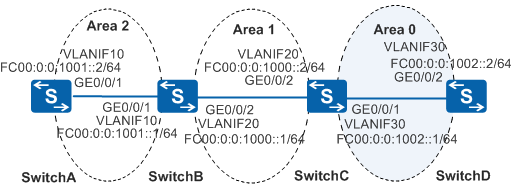
In Figure 1, OSPFv3 is enabled on all Switches, and the AS is divided into three areas. SwitchB and SwitchC serve as ABRs to forward inter-area routes. Area 2 is not directly connected to the Area 0, the backbone area. Area 1 is the area between Area 0 and Area 2.
Configure a virtual link in Area 1 where SwitchB and SwitchC are located so that SwitchA and SwitchD can communicate with each other.
Configuration Roadmap
The configuration roadmap is as follows:
Configure IPv6 addresses for interfaces.
Enable basic OSPFv3 functions on each switch.
Configure a virtual link between SwitchB and SwitchC to connect the non-backbone areas to the backbone area.
Procedure
- Add interfaces to VLANs.
# Configure SwitchA. Ensure that the configurations of SwitchB, SwitchC, and SwitchD are the same as that of SwitchA.
<HUAWEI> system-view
[HUAWEI] sysname SwitchA
[SwitchA] vlan batch 10
[SwitchA] interface gigabitethernet 0/0/1
[SwitchA-GigabitEthernet0/0/1] port link-type trunk
[SwitchA-GigabitEthernet0/0/1] port trunk allow-pass vlan 10
[SwitchA-GigabitEthernet0/0/1] quit
- Assign IPv6 addresses to the VLANIF interfaces.
# Configure SwitchA. Ensure that the configurations of SwitchB, SwitchC, and SwitchD are the same as that of SwitchA.
[SwitchA] ipv6
[SwitchA] interface vlanif 10
[SwitchA-Vlanif10] ipv6 enable
[SwitchA-Vlanif10] ipv6 address fc00:0:0:1001::2/64
[SwitchA-Vlanif10] quit
- Configure basic OSPFv3 functions.
# On SwitchA, enable OSPFv3 and set the router ID to 10.1.1.1.
[SwitchA] ospfv3
[SwitchA-ospfv3-1] router-id 10.1.1.1
[SwitchA-ospfv3-1] quit
[SwitchA] interface vlanif 10
[SwitchA-Vlanif10] ospfv3 1 area 2
[SwitchA-Vlanif10] quit
# On SwitchB, enable OSPFv3 and set the router ID to 10.2.2.2.
[SwitchB] ospfv3
[SwitchB-ospfv3-1] router-id 10.2.2.2
[SwitchB-ospfv3-1] quit
[SwitchB] interface vlanif 10
[SwitchB-Vlanif10] ospfv3 1 area 2
[SwitchB-Vlanif10] quit
[SwitchB] interface vlanif 20
[SwitchB-Vlanif20] ospfv3 1 area 1
[SwitchB-Vlanif20] quit
# On SwitchC, enable OSPFv3 and set the router ID to 10.3.3.3.
[SwitchC] ospfv3
[SwitchC-ospfv3-1] router-id 10.3.3.3
[SwitchC-ospfv3-1] quit
[SwitchC] interface vlanif 20
[SwitchC-Vlanif20] ospfv3 1 area 1
[SwitchC-Vlanif20] quit
[SwitchC] interface vlanif 30
[SwitchC-Vlanif30] ospfv3 1 area 0
[SwitchC-Vlanif30] quit
# On SwitchD, enable OSPFv3 and set the router ID to 10.4.4.4.
[SwitchD] ospfv3
[SwitchD-ospfv3-1] router-id 10.4.4.4
[SwitchD-ospfv3-1] quit
[SwitchD] interface vlanif 30
[SwitchD-Vlanif30] ospfv3 1 area 0
[SwitchD-Vlanif30] quit
# Check the OSPFv3 routing table of SwitchC. The command output shows that the routing table of SwitchC does not contain the routes of Area 2. This is because Area 2 is not directly connected to Area 0.
[SwitchC] display ospfv3 routing Codes : E2 - Type 2 External, E1 - Type 1 External, IA - Inter-Area, N - NSSA, U - Uninstalled, D - Denied by Import Policy OSPFv3 Process (1) Destination Metric Next-hop FC00:0:0:1000::/64 1 directly connected, Vlanif20 FC00:0:0:1002::/64 1 directly connected, Vlanif30 - Configure a virtual link in Area 1 where SwitchB and SwitchC are located.
# Configure SwitchB.
[SwitchB] ospfv3
[SwitchB-ospfv3-1] area 1
[SwitchB-ospfv3-1-area-0.0.0.1] vlink-peer 10.3.3.3
[SwitchB-ospfv3-1-area-0.0.0.1] return
# Configure SwitchC.
[SwitchC] ospfv3
[SwitchC-ospfv3-1] area 1
[SwitchC-ospfv3-1-area-0.0.0.1] vlink-peer 10.2.2.2
[SwitchC-ospfv3-1-area-0.0.0.1] return
- Verify the configuration.
# Check the OSPFv3 routing table of SwitchC.
<SwitchC> display ospfv3 routing

Codes : E2 - Type 2 External, E1 - Type 1 External, IA - Inter-Area,
        N - NSSA, U - Uninstalled, D - Denied by Import Policy

OSPFv3 Process (1)
   Destination                                   Metric
     Next-hop
     FC00:0:0:1000::/64                                     1
           directly connected, Vlanif20
     FC00:0:0:1000::1/128                                   1
           via FE80::4D67:0:EB7D:2, Vlanif20
     FC00:0:0:1000::2/128                                   0
           directly connected, Vlanif20
  IA FC00:0:0:1001::/64                                     2
           via FE80::4D67:0:EB7D:2, Vlanif20
     FC00:0:0:1002::/64                                     1
           directly connected, Vlanif30
Configuration Files
SwitchA configuration file
#
sysname SwitchA
#
ipv6
#
vlan batch 10
#
ospfv3 1
 router-id 10.1.1.1
#
interface Vlanif10
 ipv6 enable
 ipv6 address FC00:0:0:1001::2/64
 ospfv3 1 area 0.0.0.2
#
interface GigabitEthernet0/0/1
 port link-type trunk
 port trunk allow-pass vlan 10
#
return
SwitchB configuration file
#
sysname SwitchB
#
ipv6
#
vlan batch 10 20
#
ospfv3 1
 router-id 10.2.2.2
 area 0.0.0.1
  vlink-peer 10.3.3.3
#
interface Vlanif10
 ipv6 enable
 ipv6 address FC00:0:0:1001::1/64
 ospfv3 1 area 0.0.0.2
#
interface Vlanif20
 ipv6 enable
 ipv6 address FC00:0:0:1000::1/64
 ospfv3 1 area 0.0.0.1
#
interface GigabitEthernet0/0/1
 port link-type trunk
 port trunk allow-pass vlan 10
#
interface GigabitEthernet0/0/2
 port link-type trunk
 port trunk allow-pass vlan 20
#
return
SwitchC configuration file
#
sysname SwitchC
#
ipv6
#
vlan batch 20 30
#
ospfv3 1
 router-id 10.3.3.3
 area 0.0.0.1
  vlink-peer 10.2.2.2
#
interface Vlanif20
 ipv6 enable
 ipv6 address FC00:0:0:1000::2/64
 ospfv3 1 area 0.0.0.1
#
interface Vlanif30
 ipv6 enable
 ipv6 address FC00:0:0:1002::1/64
 ospfv3 1 area 0.0.0.0
#
interface GigabitEthernet0/0/1
 port link-type trunk
 port trunk allow-pass vlan 30
#
interface GigabitEthernet0/0/2
 port link-type trunk
 port trunk allow-pass vlan 20
#
return
SwitchD configuration file
#
sysname SwitchD
#
ipv6
#
vlan batch 30
#
ospfv3 1
 router-id 10.4.4.4
#
interface Vlanif30
 ipv6 enable
 ipv6 address FC00:0:0:1002::2/64
 ospfv3 1 area 0.0.0.0
#
interface GigabitEthernet0/0/2
 port link-type trunk
 port trunk allow-pass vlan 30
#
return