Example for Configuring PBR Based on IP Addresses
Networking Requirements
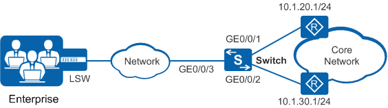
In Figure 1, the Switch on the aggregation layer is a Layer 3 forwarding device, and an LSW on the access layer serves as the user gateway. There is a reachable route between the Switch and LSW. The Switch is connected to two core routers through two links: a high-speed link with the gateway 10.1.20.1/24 and a low-speed link with the gateway 10.1.30.1/24.
The enterprise requires that the Switch forward packets from 192.168.100.0/24 and 192.168.101.0/24 to the core layer through the high-speed link and low-speed link, respectively.
Configuration Roadmap
- Create VLANs and configure interfaces to connect the enterprise' devices to external network devices.
- Configure ACL rules to separately match packets with source IP addresses 192.168.100.0/24 and 192.168.101.0/24.
- Configure traffic classifiers and bind them to ACL rules so that the Switch can differentiate packets.
- Configure traffic behaviors to redirect the packets matching different rules to 10.1.20.1/24 and 10.1.30.1/24 separately.
- Configure a traffic policy, bind it to the traffic classifiers and traffic behaviors, and apply it to the inbound direction of GE0/0/3 to implement PBR.
Procedure
- Create VLANs and configure interfaces.
# Create VLANs 100 and 200 on the Switch.
<HUAWEI> system-view
[HUAWEI] sysname Switch
[Switch] vlan batch 100 200
Configure GE0/0/1, GE0/0/2, and GE0/0/3 on the Switch as trunk interfaces, and add them to VLANs 100 and 200.
[Switch] interface gigabitethernet 0/0/1
[Switch-GigabitEthernet0/0/1] port link-type trunk
[Switch-GigabitEthernet0/0/1] port trunk allow-pass vlan 100 200
[Switch-GigabitEthernet0/0/1] quit
[Switch] interface gigabitethernet 0/0/2
[Switch-GigabitEthernet0/0/2] port link-type trunk
[Switch-GigabitEthernet0/0/2] port trunk allow-pass vlan 100 200
[Switch-GigabitEthernet0/0/2] quit
[Switch] interface gigabitethernet 0/0/3
[Switch-GigabitEthernet0/0/3] port link-type trunk
[Switch-GigabitEthernet0/0/3] port trunk allow-pass vlan 100 200
[Switch-GigabitEthernet0/0/3] quit
# Create VLANIF 100 and VLANIF 200, and configure IP addresses for them.
[Switch] interface vlanif 100
[Switch-Vlanif100] ip address 10.1.20.2 24
[Switch-Vlanif100] quit
[Switch] interface vlanif 200
[Switch-Vlanif200] ip address 10.1.30.2 24
[Switch-Vlanif200] quit
- Configure ACL rules.
# On the Switch, create advanced ACLs 3001 and 3002 to permit packets with source IP addresses 192.168.100.0/24 and 192.168.101.0/24 respectively.
[Switch] acl 3001
[Switch-acl-adv-3001] rule permit ip source 192.168.100.0 0.0.0.255
[Switch-acl-adv-3001] quit
[Switch] acl 3002
[Switch-acl-adv-3002] rule permit ip source 192.168.101.0 0.0.0.255
[Switch-acl-adv-3002] quit
- Configure traffic classifiers.
# On the Switch, create traffic classifiers c1 and c2, and bind c1 to ACL 3001 and c2 to ACL 3002.
[Switch] traffic classifier c1 operator or
[Switch-classifier-c1] if-match acl 3001
[Switch-classifier-c1] quit
[Switch] traffic classifier c2 operator or
[Switch-classifier-c2] if-match acl 3002
[Switch-classifier-c2] quit
- Configure traffic behaviors.
# On the Switch, create traffic behaviors b1 and b2 to redirect traffic to 10.1.20.1/24 and 10.1.30.1/24, respectively.
[Switch] traffic behavior b1
[Switch-behavior-b1] redirect ip-nexthop 10.1.20.1
[Switch-behavior-b1] quit
[Switch] traffic behavior b2
[Switch-behavior-b2] redirect ip-nexthop 10.1.30.1
[Switch-behavior-b2] quit
- Configure a traffic policy and apply it to an interface.
# On the Switch, create a traffic policy p1, and bind it to the traffic classifiers and traffic behaviors.
[Switch] traffic policy p1
[Switch-trafficpolicy-p1] classifier c1 behavior b1
[Switch-trafficpolicy-p1] classifier c2 behavior b2
[Switch-trafficpolicy-p1] quit
# Apply the traffic policy p1 to the inbound direction of GE0/0/3.
[Switch] interface gigabitethernet 0/0/3
[Switch-GigabitEthernet0/0/3] traffic-policy p1 inbound
[Switch-GigabitEthernet0/0/3] return
- Verify the configuration.
# Check the ACL configuration.
<Switch> display acl 3001 Advanced ACL 3001, 1 rule Acl's step is 5 rule 5 permit ip source 192.168.100.0 0.0.0.255<Switch> display acl 3002 Advanced ACL 3002, 1 rule Acl's step is 5 rule 5 permit ip source 192.168.101.0 0.0.0.255# Check the traffic classifier configuration.
<Switch> display traffic classifier user-defined
  User Defined Classifier Information:
    Classifier: c2
     Operator: OR
     Rule(s) :if-match acl 3002

    Classifier: c1
      Operator: OR
      Rule(s) : if-match acl 3001

Total classifier number is 2
# Check the traffic policy configuration.
<Switch> display traffic policy user-defined p1
  User Defined Traffic Policy Information:
  Policy: p1
   Classifier: c1
    Operator: OR
     Behavior: b1
      Redirect: no forced
        Redirect ip-nexthop
        10.1.20.1
   Classifier: c2
    Operator: OR
     Behavior: b2
      Redirect: no forced
        Redirect ip-nexthop
        10.1.30.1
Configuration Files
Switch configuration file
#
sysname Switch
#
vlan batch 100 200
#
acl number 3001
 rule 5 permit ip source 192.168.100.0 0.0.0.255
acl number 3002
 rule 5 permit ip source 192.168.101.0 0.0.0.255
#
traffic classifier c1 operator or
 if-match acl 3001
traffic classifier c2 operator or
 if-match acl 3002
#
traffic behavior b1
 redirect ip-nexthop 10.1.20.1
traffic behavior b2
 redirect ip-nexthop 10.1.30.1
#
traffic policy p1 match-order config
 classifier c1 behavior b1
 classifier c2 behavior b2
#
interface Vlanif100
 ip address 10.1.20.2 255.255.255.0
#
interface Vlanif200
 ip address 10.1.30.2 255.255.255.0
#
interface GigabitEthernet0/0/1
 port link-type trunk
 port trunk allow-pass vlan 100 200
#
interface GigabitEthernet0/0/2
 port link-type trunk
 port trunk allow-pass vlan 100 200
#
interface GigabitEthernet0/0/3
 port link-type trunk
 port trunk allow-pass vlan 100 200
 traffic-policy p1 inbound
#
return