Example for Configuring Basic IPv4 PIM-DM Functions
Networking Requirements
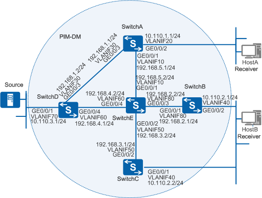
Figure 1 shows a small-scale network with densely distributed users. HostA and HostB need to receive multicast data from Source.

In this scenario, to avoid loops, ensure that all connected interfaces have STP disabled and connected interfaces are removed from VLAN 1. If STP is enabled and VLANIF interfaces of switches are used to construct a Layer 3 ring network, an interface on the network will be blocked. As a result, Layer 3 services on the network cannot run normally.
Configuration Roadmap
Since users are densely distributed on the network, PIM-DM can be deployed on the network to provide multicast services for the user hosts. After PIM-DM is configured on the network, all user hosts in a multicast group can receive multicast data sent from the multicast source to the group.
Configure IP addresses for interfaces and configure a unicast routing protocol on each switch. PIM is an intra-domain multicast routing protocol that depends on a unicast routing protocol. The multicast routing protocol can work normally only when the unicast routing protocol works normally.
Enable multicast routing on all the switches providing multicast services. Multicast routing is the prerequisite for PIM-DM configuration.
Enable PIM-DM on all switch interfaces. Other PIM-DM functions can be configured only after PIM-DM is enabled.
Enable Internet Group Management Protocol (IGMP) on the interfaces connected to user network segments. The IGMP protocol maintains group memberships. The leaf switches maintain group memberships using IGMP.
If PIM-DM and IGMP need to be enabled on the same user-side interface, enable PIM-DM and then IGMP.
Procedure
- Configure IP addresses for interfaces and configure a unicast
routing protocol on the switches.
# Configure IP addresses and masks for switch interfaces. Configure Open Shortest Path First (OSPF) on the switches to implement IP interworking between the switches and enable the switches to dynamically update routes. (The configurations of the other switches are similar to the configuration of SwitchA.)
<HUAWEI> system-view
[HUAWEI] sysname SwitchA
[SwitchA] vlan batch 10 20 30
[SwitchA] interface vlanif 10
[SwitchA-Vlanif10] ip address 192.168.5.1 24
[SwitchA-Vlanif10] quit
[SwitchA] interface vlanif 20
[SwitchA-Vlanif20] ip address 10.110.1.1 24
[SwitchA-Vlanif20] quit
[SwitchA] interface vlanif 30
[SwitchA-Vlanif30] ip address 192.168.1.1 24
[SwitchA-Vlanif30] quit
[SwitchA] interface gigabitethernet 0/0/1
[SwitchA-GigabitEthernet0/0/1] port link-type trunk
[SwitchA-GigabitEthernet0/0/1] port trunk allow-pass vlan 10
[SwitchA-GigabitEthernet0/0/1] quit
[SwitchA] interface gigabitethernet 0/0/2
[SwitchA-GigabitEthernet0/0/2] port link-type trunk
[SwitchA-GigabitEthernet0/0/2] port trunk allow-pass vlan 20
[SwitchA-GigabitEthernet0/0/2] quit
[SwitchA] interface gigabitethernet 0/0/3
[SwitchA-GigabitEthernet0/0/3] port link-type trunk
[SwitchA-GigabitEthernet0/0/3] port trunk allow-pass vlan 30
[SwitchA-GigabitEthernet0/0/3] quit
[SwitchA] ospf
[SwitchA-ospf-1] area 0
[SwitchA-ospf-1-area-0.0.0.0] network 192.168.5.0 0.0.0.255
[SwitchA-ospf-1-area-0.0.0.0] network 192.168.1.0 0.0.0.255
[SwitchA-ospf-1-area-0.0.0.0] network 10.110.1.0 0.0.0.255
[SwitchA-ospf-1-area-0.0.0.0] quit
[SwitchA-ospf-1] quit
- Enable multicast routing on all the switches and enable
PIM-DM on all interfaces.
# Enable multicast routing on all the switches and enable PIM-DM on all interfaces. (The configurations of the other switches are similar to the configuration of SwitchA.)
[SwitchA] multicast routing-enable
[SwitchA] interface vlanif 10
[SwitchA-Vlanif10] pim dm
[SwitchA-Vlanif10] quit
[SwitchA] interface vlanif 20
[SwitchA-Vlanif20] pim dm
[SwitchA-Vlanif20] quit
[SwitchA] interface vlanif 30
[SwitchA-Vlanif30] pim dm
[SwitchA-Vlanif30] quit
- Enable IGMP on the interfaces connected to user hosts.
# Enable IGMP on the user-side interface (VLANIF20) of SwitchA. (The configurations of SwitchB and SwitchC are similar to the configuration of SwitchA.)
[SwitchA] interface vlanif 20
[SwitchA-Vlanif20] igmp enable
[SwitchA-Vlanif20] quit
- Verify the configuration.
# Run the display pim interface command to check the PIM configuration and running status on switch interfaces. The following is the command output on SwitchC, indicating that PIM is running on the interfaces.
[SwitchC] display pim interface
VPN-Instance: public net
Interface      State   NbrCnt   HelloInt   DR-Pri     DR-Address
Vlanif50        up      1         30         1         192.168.3.2
Vlanif40        up      1         30         1         10.110.2.2    (local)
# Run the display pim routing-table command to check the PIM routing tables on the switches. You can see from the PIM routing tables that multicast source (10.110.3.100/24) to group (225.1.1.1/24), and HostA and HostB have joined group (225.1.1.1/24). The PIM routing tables of the switches are as follows:
[SwitchA] display pim routing-table
VPN-Instance: public net

 Total 1 (*, G) entry; 1 (S, G) entry

 (*, 225.1.1.1)
     Protocol: pim-dm, Flag: WC
     UpTime: 00:00:29
     Upstream interface: NULL
         Upstream neighbor: NULL
         RPF prime neighbor: NULL
    Downstream interface(s) information:
     Total number of downstreams: 1
         1: Vlanif20
             Protocol: igmp, UpTime: 00:00:29, Expires:never

 (10.110.3.100, 225.1.1.1)
     Protocol: pim-dm, Flag: ACT
     UpTime: 00:00:29
     Upstream interface: vlanif30
         Upstream neighbor: 192.168.1.2
         RPF prime neighbor: 192.168.1.2
    Downstream interface(s) information:
     Total number of downstreams: 1
         1: Vlanif20
             Protocol: pim-dm, UpTime: 00:00:29, Expires:-
[SwitchB] display pim routing-table VPN-Instance: public net Total 1 (*, G) entry; 1 (S, G) entry (*, 225.1.1.1) Protocol: pim-dm, Flag: WC UpTime: 00:00:29 Upstream interface: NULL Upstream neighbor: NULL RPF prime neighbor: NULL Downstream interface(s) information: Total number of downstreams: 1 1: Vlanif40 Protocol: igmp, UpTime: 00:00:29, Expires:never (10.110.3.100, 225.1.1.1) Protocol: pim-dm, Flag: ACT UpTime: 00:00:29 Upstream interface: vlanif80 Upstream neighbor: 192.168.2.2 RPF prime neighbor: 192.168.2.2 Downstream interface(s) information: Total number of downstreams: None[SwitchC] display pim routing-table VPN-Instance: public net Total 1 (*, G) entry; 1 (S, G) entry (*, 225.1.1.1) Protocol: pim-dm, Flag: WC UpTime: 00:00:29 Upstream interface: NULL Upstream neighbor: NULL RPF prime neighbor: NULL Downstream interface(s) information: Total number of downstreams: 1 1: Vlanif40 Protocol: igmp, UpTime: 00:00:29, Expires:never (10.110.3.100, 225.1.1.1) Protocol: pim-dm, Flag: ACT UpTime: 00:01:25 Upstream interface: vlanif50 Upstream neighbor: 192.168.3.2 RPF prime neighbor: 192.168.3.2 Downstream interface(s) information: Total number of downstreams: 1 1: Vlanif40 Protocol: pim-dm, UpTime: 00:01:25, Expires:-[SwitchD] display pim routing-table VPN-Instance: public net Total 0 (*, G) entry; 1 (S, G) entry (10.110.3.100, 225.1.1.1) Protocol: pim-dm, Flag: ACT UpTime: 00:00:29 Upstream interface: vlanif70 Upstream neighbor: NULL RPF prime neighbor: NULL Downstream interface(s) information: Total number of downstreams: 2 1: Vlanif30 Protocol: pim-dm, UpTime: 00:00:29, Expires:never 2: Vlanif60 Protocol: pim-dm, UpTime: 00:00:26, Expires:never[SwitchE] display pim routing-table VPN-Instance: public net Total 0 (*, G) entry; 1 (S, G) entry (10.110.3.100, 225.1.1.1) Protocol: pim-dm, Flag: ACT UpTime: 00:01:22 Upstream interface: vlanif60 Upstream neighbor: 192.168.4.1 RPF prime neighbor: 192.168.4.1 Downstream interface(s) information: Total number of downstreams: 1 1: Vlanif50 Protocol: pim-dm, UpTime: 00:01:22, Expires:never
Configuration Files
SwitchA configuration file
#
sysname SwitchA
#
vlan batch 10 20 30
#
multicast routing-enable
#
interface Vlanif10
 ip address 192.168.5.1 255.255.255.0
 pim dm
#
interface Vlanif20
 ip address 10.110.1.1 255.255.255.0
 pim dm
 igmp enable
#
interface Vlanif30
 ip address 192.168.1.1 255.255.255.0
 pim dm
#
interface GigabitEthernet0/0/1
 port link-type trunk
 port trunk allow-pass vlan 10
#
interface GigabitEthernet0/0/2
 port link-type trunk
 port trunk allow-pass vlan 20
#
interface GigabitEthernet0/0/3
 port link-type trunk
 port trunk allow-pass vlan 30
#
ospf 1
 area 0.0.0.0
  network 10.110.1.0 0.0.0.255
  network 192.168.1.0 0.0.0.255
  network 192.168.5.0 0.0.0.255
#
return
SwitchB configuration file
#
sysname SwitchB
#
vlan batch 40 80
#
multicast routing-enable
#
interface Vlanif40
 ip address 10.110.2.1 255.255.255.0
 pim dm
 igmp enable
#
interface Vlanif80
 ip address 192.168.2.1 255.255.255.0
 pim dm
#
interface GigabitEthernet0/0/1
 port link-type trunk
 port trunk allow-pass vlan 80
#
interface GigabitEthernet0/0/2
 port link-type trunk
 port trunk allow-pass vlan 40
#
ospf 1
 area 0.0.0.0
  network 10.110.2.0 0.0.0.255
  network 192.168.2.0 0.0.0.255
#
return
SwitchC configuration file
#
sysname SwitchC
#
vlan batch 40 50
#
multicast routing-enable
#
interface Vlanif40
 ip address 10.110.2.2 255.255.255.0
 pim dm
 igmp enable
#
interface Vlanif50
 ip address 192.168.3.1 255.255.255.0
 pim dm
#
interface GigabitEthernet0/0/1
 port link-type trunk
 port trunk allow-pass vlan 40
#
interface GigabitEthernet0/0/2
 port link-type trunk
 port trunk allow-pass vlan 50
#
ospf 1
 area 0.0.0.0
  network 10.110.2.0 0.0.0.255
  network 192.168.3.0 0.0.0.255
#
return
SwitchD configuration file
#
sysname SwitchD
#
vlan batch 30 60 70
#
multicast routing-enable
#
interface Vlanif30
 ip address 192.168.1.2 255.255.255.0
 pim dm
#
interface Vlanif60
 ip address 192.168.4.1 255.255.255.0
 pim dm
#
interface Vlanif70
 ip address 10.110.3.1 255.255.255.0
 pim dm
#
interface GigabitEthernet0/0/1
 port link-type trunk
 port trunk allow-pass vlan 70
#
interface GigabitEthernet0/0/3
 port link-type trunk
 port trunk allow-pass vlan 30
#
interface GigabitEthernet0/0/4
 port link-type trunk
 port trunk allow-pass vlan 60
#
ospf 1
 area 0.0.0.0
  network 10.110.3.0 0.0.0.255
  network 192.168.1.0 0.0.0.255
  network 192.168.4.0 0.0.0.255
#
return
SwitchE configuration file
#
sysname SwitchE
#
vlan batch 10 50 60 80
#
multicast routing-enable
#
interface Vlanif10
 ip address 192.168.5.2 255.255.255.0
 pim dm
#
interface Vlanif50
 ip address 192.168.3.2 255.255.255.0
 pim dm
#
interface Vlanif60
 ip address 192.168.4.2 255.255.255.0
 pim dm
#
interface Vlanif80
 ip address 192.168.2.2 255.255.255.0
 pim dm
#
interface GigabitEthernet0/0/1
 port link-type trunk
 port trunk allow-pass vlan 10
#
interface GigabitEthernet0/0/2
 port link-type trunk
 port trunk allow-pass vlan 50
#
interface GigabitEthernet0/0/3
 port link-type trunk
 port trunk allow-pass vlan 80
#
interface GigabitEthernet0/0/4
 port link-type trunk
 port trunk allow-pass vlan 60
#
ospf 1
 area 0.0.0.0
  network 192.168.2.0 0.0.0.255
  network 192.168.3.0 0.0.0.255
  network 192.168.4.0 0.0.0.255
  network 192.168.5.0 0.0.0.255
#
return