Example for Configuring IPv4 PIM-SM in the ASM Model
Networking Requirements
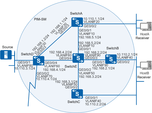
As shown in Figure 1, the shared network segment is connected to the Internet. HostA and HostB want to receive multicast data from Source.

In this scenario, to avoid loops, ensure that all connected interfaces have STP disabled and connected interfaces are removed from VLAN 1. If STP is enabled and VLANIF interfaces of switches are used to construct a Layer 3 ring network, an interface on the network will be blocked. As a result, Layer 3 services on the network cannot run normally.
Configuration Roadmap
Configure the PIM-SM protocol on the switches to enable them to provide the ASM service for user hosts on the network. Then all the hosts in a multicast group can receive multicast data sent from any sources to this group.
Configure an IP address for each interface and a unicast routing protocol. PIM is an intra-domain multicast routing protocol that depends on unicast routing protocols.
Enable the multicast function on all switches providing multicast services. Before configuring PIM-SM, you must enable the multicast function.
Enable PIM-SM on all interfaces. You can configure other PIM-SM functions only after PIM-SM is enabled.
Enable Internet Group Management Protocol (IGMP) on interfaces that connect the switch and hosts. A receiver can join and leave a multicast group by sending IGMP messages. The leaf switches maintain the multicast member relationship through IGMP.
If both PIM-SM and IGMP need to be configured on interfaces that connect the switch and hosts, you must configure PIM-SM first, and then configure IGMP.
Enable PIM silent on interfaces that connect the switch and hosts to prevent malicious hosts from simulating sending PIM Hello packets. In this manner, security of PIM-SM domain is ensured.
If the user host network segment connects to multiple switches, do not enable PIM silent on interfaces that connect these switches and user hosts. For example, PIM Silent cannot be enabled on SwitchB and SwitchC in the figure.
Configure the RP. In PIM-SM domain, RP is essential in providing ASM services and helps forward multicast data. You are advised to configure RP on switches that have more multicast flows. For example, you can configure RP on SwitchE in the figure.
Configure the BSR boundary on interfaces connected to the Internet. The Bootstrap message cannot pass through the BSR boundary; therefore, the BSR serves only this PIM-SM domain. In this manner, multicast services can be controlled effectively.
Procedure
- Configure an IP address for each interface and a unicast
routing protocol.
# Configure the IP address and mask for each interface shown in Figure 1, and configure Open Shortest Path First (OSPF) on each switch to ensure that switches can communicate at the network layer and can dynamically update routes through the unicast routing protocol. The configuration of SwitchB, SwitchC, SwitchD, and SwitchE are similar to the configuration of SwitchA, and are not provided here.
<HUAWEI> system-view
[HUAWEI] sysname SwitchA
[SwitchA] vlan batch 10 20 30
[SwitchA] interface gigabitethernet0/0/1
[SwitchA-GigabitEthernet0/0/1] port link-type trunk
[SwitchA-GigabitEthernet0/0/1] port trunk allow-pass vlan 10
[SwitchA-GigabitEthernet0/0/1] quit
[SwitchA] interface gigabitethernet0/0/2
[SwitchA-GigabitEthernet0/0/2] port link-type trunk
[SwitchA-GigabitEthernet0/0/2] port trunk allow-pass vlan 20
[SwitchA-GigabitEthernet0/0/2] quit
[SwitchA] interface gigabitethernet0/0/3
[SwitchA-GigabitEthernet0/0/3] port link-type trunk
[SwitchA-GigabitEthernet0/0/3] port trunk allow-pass vlan 30
[SwitchA-GigabitEthernet0/0/3] quit
[SwitchA] interface vlanif 10
[SwitchA-Vlanif10] ip address 192.168.5.1 24
[SwitchA-Vlanif10] quit
[SwitchA] interface vlanif 20
[SwitchA-Vlanif20] ip address 10.110.1.1 24
[SwitchA-Vlanif20] quit
[SwitchA] interface vlanif 30
[SwitchA-Vlanif30] ip address 192.168.1.1 24
[SwitchA-Vlanif30] quit
[SwitchA] ospf
[SwitchA-ospf-1] area 0
[SwitchA-ospf-1-area-0.0.0.0] network 10.110.1.0 0.0.0.255
[SwitchA-ospf-1-area-0.0.0.0] network 192.168.1.0 0.0.0.255
[SwitchA-ospf-1-area-0.0.0.0] network 192.168.5.0 0.0.0.255
[SwitchA-ospf-1-area-0.0.0.0] quit
[SwitchA-ospf-1] quit
- Enable multicast, and enable PIM-SM on all interfaces.
# Enable multicast on all switches and PIM-SM on all interfaces. The configuration of SwitchB, SwitchC, SwitchD, and SwitchE are similar to the configuration of SwitchA, and are not provided here.
[SwitchA] multicast routing-enable
[SwitchA] interface vlanif 10
[SwitchA-Vlanif10] pim sm
[SwitchA-Vlanif10] quit
[SwitchA] interface vlanif 20
[SwitchA-Vlanif20] pim sm
[SwitchA-Vlanif20] quit
[SwitchA] interface vlanif 30
[SwitchA-Vlanif30] pim sm
[SwitchA-Vlanif30] quit
- Enable IGMP on interfaces that connect the switch and hosts.
# Enable IGMP on interfaces that connect SwitchA and user hosts. The configuration of SwitchB and SwitchC are similar to the configuration of SwitchA, and are not provided here.
[SwitchA] interface vlanif 20
[SwitchA-Vlanif20] igmp enable
[SwitchA-Vlanif20] quit
- Enable PIM silent on interfaces on SwitchA.
[SwitchA] interface vlanif 20
[SwitchA-Vlanif20] pim silent
[SwitchA-Vlanif20] quit
- Configure the rendezvous point (RP).
RP can be configured in two modes: static RP and dynamic RP. The static RP can be configured together with the dynamic RP. You can also configure only the static RP or the dynamic RP. When the static RP and the dynamic RP are configured simultaneously, you can adjust parameters to specify the preferred RP.
This example shows how to configure both the static RP and the dynamic RP and to specify the dynamic RP as the preferred RP and the static RP as the standby RP.
# Configure the dynamic RP. Configure C-RP and C-BSR on one or more switches in the PIM-SM domain. In this example, specify SwitchE as both the C-RP and the C-BSR. Configure the address range of the multicast group that the RP serves on SwitchE and configure the C-BSR and C-RP on the interface.
[SwitchE] acl number 2008
[SwitchE-acl-basic-2008] rule permit source 225.1.1.0 0.0.0.255
[SwitchE-acl-basic-2008] quit
[SwitchE] pim
[SwitchE-pim] c-bsr vlanif 90
[SwitchE-pim] c-rp vlanif 90 group-policy 2008
[SwitchE-pim] quit
# Configure the static RP. Specify the address of static RP on all interfaces. Perform the following configurations on SwitchA. The configuration of SwitchB, SwitchC, SwitchD, and SwitchE are similar to the configuration of SwitchA, and are not provided here.
If you enter preferred in the static-rp X.X.X.X command, the static RP is selected as the RP in the PIM-SM domain.
[SwitchA] pim
[SwitchA-pim] static-rp 192.168.4.2
[SwitchA-pim] quit
- Configure the BSR boundary on interfaces that connect SwitchD
to the Internet.
[SwitchD] interface vlanif 70
[SwitchD-Vlanif70] pim bsr-boundary
[SwitchD-Vlanif70] quit
- Verify the configuration.
# Run the display pim interface command to check the PIM configuration and status. In this example, the PIM information on SwitchC is displayed as follows:
[SwitchC] display pim interface
VPN-Instance: public net
Interface      State   NbrCnt   HelloInt   DR-Pri     DR-Address
Vlanif50        up      1         30         1         192.168.3.2
Vlanif40        up      1         30         1         10.110.2.2    (local)
# Run the display pim bsr-info command to check information about the BSR selection on the switch. For example, BSR information on SwitchA and SwitchE is displayed as follows (C-BSR information is also displayed on SwitchE).
[SwitchA] display pim bsr-info
VPN-Instance: public net
 Elected AdminScoped BSR Count: 0
 Elected BSR Address: 192.168.2.2
     Priority: 0
     Hash mask length: 30
     State: Accept Preferred
     Scope: Not scoped
     Uptime: 01:40:40
     Expires: 00:01:42
     C-RP Count: 1
[SwitchE] display pim bsr-info VPN-Instance: public net Elected AdminScoped BSR Count: 0 Elected BSR Address: 192.168.2.2 Priority: 0 Hash mask length: 30 State: Elected Scope: Not scoped Uptime: 00:00:18 Next BSR message scheduled at :00:01:42 C-RP Count: 1 Candidate AdminScoped BSR Count: 0 Candidate BSR Address: 192.168.2.2 Priority: 0 Hash mask length: 30 State: Elected Scope: Not scoped Wait to be BSR: 0# Run the display pim rp-info command to check the RP information on SwitchA. In this example, the RP information on SwitchA is displayed as follows:
[SwitchA] display pim rp-info
VPN-Instance: public net
 PIM-SM BSR RP Number:1
 Group/MaskLen: 225.1.1.0/24
     RP: 192.168.2.2
     Priority: 0
     Uptime: 00:45:13
     Expires: 00:02:17
 PIM SM static RP Number:1
     Static RP: 192.168.4.2
# Run the display pim routing-table command to view the PIM routing table. The multicast source 10.110.3.100/24 sends message to the multicast group 225.1.1.1/24. Host A and Host B join the multicast group 225.1.1.1/24. Detailed information is displayed as follows:
By default, after the receiver's DR receives the first multicast data, an SPT switchover is performed and (S, G) routing entries are created. Therefore, (S, G) routing entries displayed on the switch are (S, G) entries after the SPT switchover.
[SwitchA] display pim routing-table
VPN-Instance: public net
 Total 1 (*, G) entry; 1 (S, G) entry

(*, 225.1.1.1)
     RP: 192.168.2.2
     Protocol: pim-sm, Flag: WC
     UpTime: 00:13:46
     Upstream interface: Vlanif10
         Upstream neighbor: 192.168.5.2
         RPF prime neighbor: 192.168.5.2
     Downstream interface(s) information:
     Total number of downstreams: 1
         1: Vlanif20
             Protocol: igmp, UpTime: 00:13:46, Expires:-

(10.110.3.100, 225.1.1.1)
     RP: 192.168.2.2
     Protocol: pim-sm, Flag: RPT SPT ACT
     UpTime: 00:00:42
     Upstream interface: Vlanif30
         Upstream neighbor: 192.168.1.2
         RPF prime neighbor: 192.168.1.2
    Downstream interface(s) information:
     Total number of downstreams: 1
         1: Vlanif20
             Protocol: pim-sm, UpTime: 00:00:42, Expires:-
[SwitchB] display pim routing-table
VPN-Instance: public net
 Total 1 (*, G) entry; 1 (S, G) entry

(*, 225.1.1.1)
     RP: 192.168.2.2
     Protocol: pim-sm, Flag: WC
     UpTime: 00:10:12
     Upstream interface: Vlanif90
         Upstream neighbor: 192.168.2.2
         RPF prime neighbor: 192.168.2.2
     Downstream interface(s) information: None

(10.110.3.100, 225.1.1.1)
     RP: 192.168.2.2
     Protocol: pim-sm, Flag: ACT
     UpTime: 00:00:42
     Upstream interface: Vlanif90
         Upstream neighbor: 192.168.2.2
         RPF prime neighbor: 192.168.2.2
    Downstream interface(s) information: None

[SwitchC] display pim routing-table
 VPN-Instance: public net
 Total 1 (*, G) entry; 1 (S, G) entry

 (*, 225.1.1.1)
     RP: 192.168.2.2
     Protocol: pim-sm, Flag: WC
     UpTime: 00:01:25
     Upstream interface: Vlanif50
         Upstream neighbor: 192.168.3.2
         RPF prime neighbor: 192.168.3.2
     Downstream interface(s) information:
     Total number of downstreams: 1
         1: Vlanif40
             Protocol: igmp, UpTime: 00:01:25, Expires:-

 (10.110.3.100, 225.1.1.1)
     RP: 192.168.2.2
     Protocol: pim-sm, Flag: SPT ACT
     UpTime: 00:01:25
     Upstream interface: Vlanif50
         Upstream neighbor: 192.168.3.2
         RPF prime neighbor: 192.168.3.2
     Downstream interface(s) information:
     Total number of downstreams: 1
         1: Vlanif40
             Protocol: pim-sm, UpTime: 00:01:25, Expires:-

[SwitchD] display pim routing-table
VPN-Instance: public net
 Total 0 (*, G) entry; 1 (S, G) entry

 (10.110.3.100, 225.1.1.1)
     RP: 192.168.2.2
     Protocol: pim-sm, Flag: SPT LOC ACT
     UpTime: 00:00:42
     Upstream interface: Vlanif80
         Upstream neighbor: NULL
         RPF prime neighbor: NULL
     Downstream interface(s) information:
     Total number of downstreams: 2
         1: Vlanif30
             Protocol: pim-sm, UpTime: 00:01:22, Expires:-
         2: Vlanif60
             Protocol: pim-sm, UpTime: 00:00:42, Expires:-

[SwitchE] display pim routing-table
VPN-Instance: public net
 Total 1 (*, G) entry; 1 (S, G) entry

 (*, 225.1.1.1)
     RP: 192.168.2.2 (local)
     Protocol: pim-sm, Flag: WC
     UpTime: 00:13:16
     Upstream interface: Register
         Upstream neighbor: NULL
         RPF prime neighbor: NULL
     Downstream interface(s) information:
     Total number of downstreams: 2
         1: Vlanif10
             Protocol: pim-sm, UpTime: 00:12:13, Expires: 00:02:21
         2: Vlanif50
             Protocol: pim-sm, UpTime: 00:13:16, Expires: 00:03:22

(10.110.3.100, 225.1.1.1)
     RP: 192.168.2.2
     Protocol: pim-sm, Flag: SPT ACT
     UpTime: 00:01:22
     Upstream interface: Vlanif60
         Upstream neighbor: 192.168.4.1
         RPF prime neighbor: 192.168.4.1
     Downstream interface(s) information:
     Total number of downstreams: 1
         1: Vlanif50
             Protocol: pim-sm, UpTime: 00:01:22, Expires:-
Configuration Files
SwitchA configuration file
#
sysname SwitchA
#
vlan batch 10 20 30
#
multicast routing-enable
#
interface Vlanif10
 ip address 192.168.5.1 255.255.255.0
 pim sm
#
interface Vlanif20
 ip address 10.110.1.1 255.255.255.0
 pim silent
 pim sm
 igmp enable
#
interface Vlanif30
 ip address 192.168.1.1 255.255.255.0
 pim sm
#
interface GigabitEthernet0/0/1
 port link-type trunk
 port trunk allow-pass vlan 10
#
interface GigabitEthernet0/0/2
 port link-type trunk
 port trunk allow-pass vlan 20
#
interface GigabitEthernet0/0/3
 port link-type trunk
 port trunk allow-pass vlan 30
#
ospf 1
 area 0.0.0.0
  network 10.110.1.0 0.0.0.255
  network 192.168.1.0 0.0.0.255
  network 192.168.5.0 0.0.0.255
#
pim
 static-rp 192.168.4.2
#
return
SwitchB configuration file
#
sysname SwitchB
#
vlan batch 40 90
#
multicast routing-enable
#
interface Vlanif40
 ip address 10.110.2.1 255.255.255.0
 pim sm
 igmp enable
#
interface Vlanif90
 ip address 192.168.2.1 255.255.255.0
 pim sm
#
interface GigabitEthernet0/0/1
 port link-type trunk
 port trunk allow-pass vlan 90
#
interface GigabitEthernet0/0/2
 port link-type trunk
 port trunk allow-pass vlan 40
#
ospf 1
 area 0.0.0.0
  network 10.110.2.0 0.0.0.255
  network 192.168.2.0 0.0.0.255
#
pim
 static-rp 192.168.4.2
#
return
SwitchC configuration file
#
sysname SwitchC
#
vlan batch 40 50
#
multicast routing-enable
#
interface Vlanif40
 ip address 10.110.2.2 255.255.255.0
 pim sm
 igmp enable
#
interface Vlanif50
 ip address 192.168.3.1 255.255.255.0
 pim sm
#
interface GigabitEthernet0/0/1
 port link-type trunk
 port trunk allow-pass vlan 40
#
interface GigabitEthernet0/0/2
 port link-type trunk
 port trunk allow-pass vlan 50
#
ospf 1
 area 0.0.0.0
  network 10.110.2.0 0.0.0.255
  network 192.168.3.0 0.0.0.255
#
pim
 static-rp 192.168.4.2
#
return
SwitchD configuration file
#
sysname SwitchD
#
vlan batch 30 60 70 80
#
multicast routing-enable
#
interface Vlanif30
 ip address 192.168.1.2 255.255.255.0
 pim sm
#
interface Vlanif60
 ip address 192.168.4.1 255.255.255.0
 pim sm
#
interface Vlanif70
 ip address 10.110.4.1 255.255.255.0
 pim bsr-boundary
 pim sm
#
interface Vlanif80
 ip address 10.110.3.1 255.255.255.0
 pim sm
#
interface GigabitEthernet0/0/1
 port link-type trunk
 port trunk allow-pass vlan 80
#
interface GigabitEthernet0/0/2
 port link-type trunk
 port trunk allow-pass vlan 70
#
interface GigabitEthernet0/0/3
 port link-type trunk
 port trunk allow-pass vlan 30
#
interface GigabitEthernet0/0/4
 port link-type trunk
 port trunk allow-pass vlan 60
#
ospf 1
 area 0.0.0.0
  network 10.110.3.0 0.0.0.255
  network 10.110.4.0 0.0.0.255
  network 192.168.1.0 0.0.0.255
  network 192.168.4.0 0.0.0.255
#
pim
 static-rp 192.168.4.2
#
return
SwitchE configuration file
#
sysname SwitchE
#
vlan batch 10 50 60 90
#
multicast routing-enable
#
acl number 2008
 rule 5 permit source 225.1.1.0 0.0.0.255
#
interface Vlanif10
 ip address 192.168.5.2 255.255.255.0
 pim sm
#
interface Vlanif50
 ip address 192.168.3.2 255.255.255.0
 pim sm
#
interface Vlanif60
 ip address 192.168.4.2 255.255.255.0
 pim sm
#
interface Vlanif90
 ip address 192.168.2.2 255.255.255.0
 pim sm
#
interface GigabitEthernet0/0/1
 port link-type trunk
 port trunk allow-pass vlan 10
#
interface GigabitEthernet0/0/2
 port link-type trunk
 port trunk allow-pass vlan 50
#
interface GigabitEthernet0/0/3
 port link-type trunk
 port trunk allow-pass vlan 90
#
interface GigabitEthernet0/0/4
 port link-type trunk
 port trunk allow-pass vlan 60
#
ospf 1
 area 0.0.0.0
  network 192.168.2.0 0.0.0.255
  network 192.168.3.0 0.0.0.255
  network 192.168.4.0 0.0.0.255
  network 192.168.5.0 0.0.0.255
#
pim
 c-bsr Vlanif90
 c-rp Vlanif90 group-policy 2008
 static-rp 192.168.4.2
#
return