Example for Configuring PIM BFD
Networking Requirements
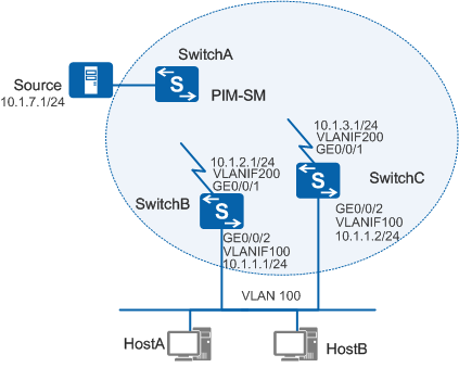
In Figure 1, basic PIM-SM configuration has been completed on the Switches. User hosts receive multicast data from the multicast source. SwitchA is the source designated router (DR). SwitchB and SwitchC are connected to the user host network segment. When the receiver DR changes, other switches are required to fast respond to the change.
You can set up Bidirectional Forwarding Detection (BFD) sessions on the user host network segment so that switches can fast respond to the change of the DR. In addition, you can configure the DR switchover delay. When a Switch is added to the network segment and may become a DR, the multicast routing table of the original DR is reserved until routing entries of the new DR are created. Therefore, the packet loss due to the delay in creating multicast entries is prevented.

After the DR switchover delay is configured, the downstream receivers will receive two copies of the same data during the DR switchover, which will trigger the assert mechanism. To prevent triggering the assert mechanism, it is recommended that DR switchover delay is not configured.
Configuration Roadmap
The configuration roadmap is as follows:
Configure PIM BFD on interfaces that connect the Switch to the user host network segment.
Configure the PIM DR switchover delay on interfaces that connect the Switch to the user host network segment.
This configuration example describes only relevant PIM-SM BFD commands.
Procedure
- Enable BFD globally and configure PIM BFD in the interface view.
Enable BFD globally on SwitchB and SwitchC and enable PIM BFD on interfaces connecting to the user host network segment and configure PIM BFD parameters. The configuration of SwitchC is similar to the configuration of SwitchB, and is not mentioned here.
[SwitchB] bfd
[SwitchB-bfd] quit
[SwitchB] interface vlanif 100
[SwitchB-Vlanif100] pim bfd enable
[SwitchB-Vlanif100] pim bfd min-tx-interval 100 min-rx-interval 100 detect-multiplier 3
- Configure the PIM DR switchover delay.
# Configure the PIM DR delay on SwitchB and SwitchC. The configuration of SwitchC is similar to the configuration of SwitchB, and is not mentioned.
[SwitchB-Vlanif100] pim timer dr-switch-delay 20 - Verify the configuration.
Run the display pim interface verbose command to check information on the PIM-enabled interface. The information about the PIM-enabled interface on SwitchB indicates that the DR on the host network segment is SwitchC. PIM BFD is enabled on the interface and the switchover delay is configured.
<SwitchB> display pim interface vlanif100 verbose
VPN-Instance: public net
 Interface: Vlanif100, 10.1.1.1
     PIM version: 2
     PIM mode: Sparse
     PIM state: up
     PIM DR: 10.1.1.2
     PIM DR Priority (configured): 1
     PIM neighbor count: 1
     PIM hello interval: 30 s
     PIM LAN delay (negotiated): 500 ms
     PIM LAN delay (configured): 500 ms
     PIM hello override interval (negotiated): 2500 ms
     PIM hello override interval (configured): 2500 ms
     PIM Silent: disabled
     PIM neighbor tracking (negotiated): disabled
     PIM neighbor tracking (configured): disabled
     PIM generation ID: 0XF5712241
     PIM require-GenID: disabled
     PIM hello hold interval: 105 s
     PIM assert hold interval: 180 s
     PIM triggered hello delay: 5 s
     PIM J/P interval: 60 s
     PIM J/P hold interval: 210 s
     PIM BSR domain border: disabled
     PIM BFD: enabled
     PIM BFD min-tx-interval: 100 ms
     PIM BFD min-rx-interval: 100 ms
     PIM BFD detect-multiplier: 3
     PIM dr-switch-delay timer : 20 s
     Number of routers on link not using DR priority: 0
     Number of routers on link not using LAN delay: 0
     Number of routers on link not using neighbor tracking: 2
     ACL of PIM neighbor policy: -
     ACL of PIM ASM join policy: -
     ACL of PIM SSM join policy: -
     ACL of PIM join policy: -
# Run the display pim bfd session command to check information about the BFD session on SwitchB. You can check whether the BRD session is set up.
<SwitchB> display pim bfd session
VPN-Instance: public net
Total 1 BFD session Created

Vlanif100 (10.1.1.1): Total 1 BFD session Created

Neighbor     ActTx(ms)     ActRx(ms)     ActMulti     Local/Remote     State
10.1.1.2     100           100           3            8192/8192        Up
# Run the display pim routing-table command to view the PIM routing table. SwitchC functions as the DR. The (S, G) and (*, G) entries exist. The following information is displayed.
<SwitchC> display pim routing-table
VPN-Instance: public net
 Total 1 (*, G) entry; 1 (S, G) entry

(*, 225.1.1.1)
     RP: 10.1.5.2
     Protocol: pim-sm, Flag: WC
     UpTime: 00:13:46
     Upstream interface: Vlanif200
         Upstream neighbor: 10.1.2.2
         RPF prime neighbor: 10.1.2.2
     Downstream interface(s) information:
     Total number of downstreams: 1
         1: Vlanif100
             Protocol: igmp, UpTime: 00:13:46, Expires:-
(10.1.7.1, 225.1.1.1)
     RP: 10.1.5.2
     Protocol: pim-sm, Flag: SPT ACT
     UpTime: 00:00:42
     Upstream interface: Vlanif200
         Upstream neighbor: 10.1.2.2
         RPF prime neighbor: 10.1.2.2
     Downstream interface(s) information:
     Total number of downstreams: 1
         1: Vlanif100
             Protocol: pim-sm, UpTime: 00:00:42, Expires:-
Configuration Files
SwitchA needs to be configured with only basic PIM SM functions. The configuration file is not provided here.
- SwitchB has the following configuration file. The configuration file of SwitchC is similar to that of SwitchB and is not provided here.
#
 sysname SwitchB
#
 vlan batch 100 200
#
 multicast routing-enable
#
bfd
#
interface Vlanif100
 ip address 10.1.1.1 255.255.255.0
 pim timer dr-switch-delay 20
 pim sm
 pim bfd enable
 pim bfd min-tx-interval 100 min-rx-interval 100
 igmp enable
#
interface Vlanif200
 ip address 10.1.2.1 255.255.255.0
 pim sm
#
interface GigabitEthernet0/0/1
 port link-type trunk
 port trunk allow-pass vlan 200
#
interface GigabitEthernet0/0/2
 port link-type hybrid
 port hybrid pvid vlan 100
 port hybrid untagged vlan 100
#
ospf 1
 area 0.0.0.0
  network 10.1.1.0 0.0.0.255
  network 10.1.2.0 0.0.0.255
#
return