Example for Configuring PIM over GRE
Networking Requirements
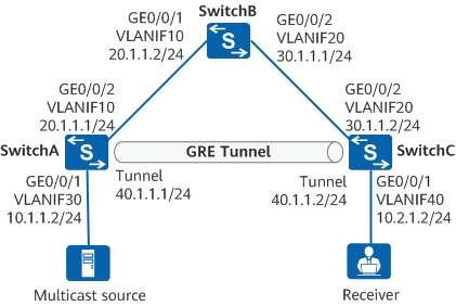
Multicast services need to be deployed on the network shown in Figure 1. SwitchB does not support multicast protocols, so a GRE tunnel needs to be established between SwitchA and SwitchC to transmit multicast traffic.
Configuration Roadmap
The configuration roadmap is as follows:
Configure OSPF on SwitchA, SwitchB, and SwitchC to implement route reachability between them.
Create tunnel interfaces on SwitchA and SwitchC to establish a GRE tunnel between them.
Enable PIM on the tunnel interfaces to enable multicast packets to be transmitted over the GRE tunnel.
Procedure
- Configure an IP address for each interface.
# Configure SwitchA.
<HUAWEI> system-view
[HUAWEI] sysname SwitchA
[SwitchA] vlan batch 10 30
[SwitchA] interface gigabitethernet 0/0/1
[SwitchA-GigabitEthernet0/0/1] port link-type access
[SwitchA-GigabitEthernet0/0/1] port default vlan 30
[SwitchA-GigabitEthernet0/0/1] quit
[SwitchA] interface gigabitethernet 0/0/2
[SwitchA-GigabitEthernet0/0/2] port link-type trunk
[SwitchA-GigabitEthernet0/0/2] port trunk allow-pass vlan 10
[SwitchA-GigabitEthernet0/0/2] quit
[SwitchA] interface vlanif 30
[SwitchA-Vlanif30] ip address 10.1.1.2 24
[SwitchA-Vlanif30] quit
[SwitchA] interface vlanif 10
[SwitchA-Vlanif10] ip address 10.20.1.1 24
[SwitchA-Vlanif10] quit
# Configure SwitchB.
<HUAWEI> system-view
[HUAWEI] sysname SwitchB
[SwitchB] vlan batch 10 20
[SwitchB] interface gigabitethernet 0/0/1
[SwitchB-GigabitEthernet0/0/1] port link-type trunk
[SwitchB-GigabitEthernet0/0/1] port trunk allow-pass vlan 10
[SwitchB-GigabitEthernet0/0/1] quit
[SwitchB] interface gigabitethernet 0/0/2
[SwitchB-GigabitEthernet0/0/2] port link-type trunk
[SwitchB-GigabitEthernet0/0/2] port trunk allow-pass vlan 20
[SwitchB-GigabitEthernet0/0/2] quit
[SwitchB] interface vlanif 10
[SwitchB-Vlanif10] ip address 10.20.1.2 24
[SwitchB-Vlanif10] quit
[SwitchB] interface vlanif 20
[SwitchB-Vlanif20] ip address 10.30.1.1 24
[SwitchB-Vlanif20] quit
# Configure SwitchC.
<HUAWEI> system-view
[HUAWEI] sysname SwitchC
[SwitchC] vlan batch 20 40
[SwitchC] interface gigabitethernet 0/0/2
[SwitchC-GigabitEthernet0/0/2] port link-type trunk
[SwitchC-GigabitEthernet0/0/2] port trunk allow-pass vlan 20
[SwitchC-GigabitEthernet0/0/2] quit
[SwitchC] interface gigabitethernet 0/0/1
[SwitchC-GigabitEthernet0/0/1] port link-type access
[SwitchC-GigabitEthernet0/0/1] port default vlan 40
[SwitchC-GigabitEthernet0/0/1] quit
[SwitchC] interface vlanif 20
[SwitchC-Vlanif20] ip address 10.30.1.2 24
[SwitchC-Vlanif20] quit
[SwitchC] interface vlanif 40
[SwitchC-Vlanif40] ip address 10.2.1.2 24
[SwitchC-Vlanif40] quit
- Configuring OSPF on the devices so they can communicate with each other.
# Configure SwitchA.
[SwitchA] ospf 1
[SwitchA-ospf-1] area 0
[SwitchA-ospf-1-area-0.0.0.0] network 10.20.1.0 0.0.0.255
[SwitchA-ospf-1-area-0.0.0.0] quit
[SwitchA-ospf-1] quit
# Configure SwitchB.
[SwitchB] ospf 1
[SwitchB-ospf-1] area 0
[SwitchB-ospf-1-area-0.0.0.0] network 10.20.1.0 0.0.0.255
[SwitchB-ospf-1-area-0.0.0.0] network 10.30.1.0 0.0.0.255
[SwitchB-ospf-1-area-0.0.0.0] quit
[SwitchB-ospf-1] quit
# Configure SwitchC.
[SwitchC] ospf 1
[SwitchC-ospf-1] area 0
[SwitchC-ospf-1-area-0.0.0.0] network 10.30.1.0 0.0.0.255
[SwitchC-ospf-1-area-0.0.0.0] quit
[SwitchC-ospf-1] quit
# After the configuration is complete, run the display ip routing-table command on SwitchA and SwitchC. The command output shows that they have learned the OSPF routes destined for the network segment of the peer.
[SwitchA] display ip routing-table
Route Flags: R - relay, D - download to fib
------------------------------------------------------------------------------
Routing Tables: Public
         Destinations : 3       Routes : 3

Destination/Mask    Proto   Pre  Cost      Flags NextHop         Interface

       10.20.1.0/24  Direct  0    0           D   10.20.1.1        Vlanif10
       10.20.1.1/32  Direct  0    0           D   127.0.0.1        Vlanif10
       10.30.1.0/24  OSPF    10   2           D   10.20.1.2        Vlanif10
[SwitchC] display ip routing-table Route Flags: R - relay, D - download to fib ------------------------------------------------------------------------------ Routing Tables: Public Destinations : 3 Routes : 3 Destination/Mask Proto Pre Cost Flags NextHop Interface 10.20.1.0/24 OSPF 10 2 D 10.30.1.1 Vlanif20 10.30.1.0/24 Direct 0 0 D 10.30.1.2 Vlanif20 10.30.1.2/32 Direct 0 0 D 127.0.0.1 Vlanif20 - Configure tunnel interfaces.
# Configure SwitchA.
[SwitchA] interface tunnel 1
[SwitchA-Tunnel1] tunnel-protocol gre
[SwitchA-Tunnel1] ip address 10.40.1.1 255.255.255.0
[SwitchA-Tunnel1] source 10.20.1.1
[SwitchA-Tunnel1] destination 10.30.1.2
[SwitchA-Tunnel1] quit
# Configure SwitchC.
[SwitchC] interface tunnel 1
[SwitchC-Tunnel1] tunnel-protocol gre
[SwitchC-Tunnel1] ip address 10.40.1.2 255.255.255.0
[SwitchC-Tunnel1] source 10.30.1.2
[SwitchC-Tunnel1] destination 10.20.1.1
[SwitchC-Tunnel1] quit
# After the configuration is complete, the tunnel interfaces turn Up and can ping each other. The ping command output on SwitchA is provided as an example:
[SwitchA] ping -a 10.40.1.1 10.40.1.2
  PING 40.1.1.2: 56  data bytes, press CTRL_C to break
    Reply from 10.40.1.2: bytes=56 Sequence=1 ttl=255 time=1 ms
    Reply from 10.40.1.2: bytes=56 Sequence=2 ttl=255 time=1 ms
    Reply from 10.40.1.2: bytes=56 Sequence=3 ttl=255 time=1 ms
    Reply from 10.40.1.2: bytes=56 Sequence=4 ttl=255 time=1 ms
    Reply from 10.40.1.2: bytes=56 Sequence=5 ttl=255 time=1 ms

  --- 10.40.1.2 ping statistics ---
    5 packet(s) transmitted
    5 packet(s) received
    0.00% packet loss
    round-trip min/avg/max = 1/1/1 ms
# The routing tables of the two devices contain the routing entries of the tunnel interfaces.
[SwitchA] display ip routing-table
Route Flags: R - relay, D - download to fib
------------------------------------------------------------------------------
Routing Tables: Public
         Destinations : 5       Routes : 5

Destination/Mask    Proto   Pre  Cost      Flags NextHop         Interface

       10.20.1.0/24  Direct  0    0           D   10.20.1.1        Vlanif10
       10.20.1.1/32  Direct  0    0           D   127.0.0.1        Vlanif10
       10.30.1.0/24  OSPF    10   2           D   10.20.1.2        Vlanif10
       10.40.1.0/24  Direct  0    0           D   10.40.1.1        Tunnel1
       10.40.1.1/32  Direct  0    0           D   127.0.0.1        Tunnel1
[SwitchC] display ip routing-table Route Flags: R - relay, D - download to fib ------------------------------------------------------------------------------ Routing Tables: Public Destinations : 5 Routes : 5 Destination/Mask Proto Pre Cost Flags NextHop Interface 10.20.1.0/24 OSPF 10 2 D 10.30.1.1 Vlanif20 10.30.1.0/24 Direct 0 0 D 10.30.1.2 Vlanif20 10.30.1.2/32 Direct 0 0 D 127.0.0.1 Vlanif20 10.40.1.0/24 Direct 0 0 D 10.40.1.2 Tunnel1 10.40.1.2/32 Direct 0 0 D 127.0.0.1 Tunnel1 - Configure OSPF on tunnel interfaces.
# Configure SwitchA.
[SwitchA] ospf 2
[SwitchA-ospf-2] area 0
[SwitchA-ospf-2-area-0.0.0.0] network 10.40.1.0 0.0.0.255
[SwitchA-ospf-2-area-0.0.0.0] network 10.1.1.0 0.0.0.255
[SwitchA-ospf-2-area-0.0.0.0] quit
[SwitchA-ospf-2] quit
# Configure SwitchC.
[SwitchC] ospf 2
[SwitchC-ospf-2] area 0
[SwitchC-ospf-2-area-0.0.0.0] network 10.40.1.0 0.0.0.255
[SwitchC-ospf-2-area-0.0.0.0] network 10.2.1.0 0.0.0.255
[SwitchC-ospf-2-area-0.0.0.0] quit
[SwitchC-ospf-2] quit
# After the configuration is complete, run the display ip routing-table protocol ospf command on SwitchA and SwitchC. The command output shows that each device has generated an OSPF route destined for the user network segment through the tunnel interface, with the corresponding VLANIF interface as the next hop.
[SwitchA] display ip routing-table protocol ospf
Route Flags: R - relay, D - download to fib
------------------------------------------------------------------------------
Public routing table : OSPF
         Destinations : 2        Routes : 2

OSPF routing table status : <Active>
         Destinations : 2        Routes : 2

Destination/Mask    Proto   Pre  Cost      Flags NextHop         Interface

       10.20.1.0/24  OSPF    10   1563        D   10.40.1.2        Tunnel1
       10.30.1.0/24  OSPF    10   2           D   10.20.1.2        Vlanif10

OSPF routing table status : <Inactive>
         Destinations : 0        Routes : 0
[SwitchC] display ip routing-table protocol ospf Route Flags: R - relay, D - download to fib ------------------------------------------------------------------------------ Public routing table : OSPF Destinations : 2 Routes : 2 OSPF routing table status : <Active> Destinations : 2 Routes : 2 Destination/Mask Proto Pre Cost Flags NextHop Interface 10.1.1.0/24 OSPF 10 1563 D 10.40.1.1 Tunnel1 10.20.1.0/24 OSPF 10 2 D 10.30.1.1 Vlanif20 OSPF routing table status : <Inactive> Destinations : 0 Routes : 0 - Configure PIM.
# Enable PIM on the VLANIF and tunnel interfaces on SwitchA.
[SwitchA] multicast routing-enable
[SwitchA] interface vlanif 30
[SwitchA-Vlanif30] pim sm
[SwitchA-Vlanif30] quit
[SwitchA] interface tunnel 1
[SwitchA-Tunnel1] pim sm
[SwitchA-Tunnel1] quit
# Specify the static RP address on SwitchA, which is the IP address of the tunnel interface on SwitchA.
[SwitchA] pim
[SwitchA-pim] static-rp 10.40.1.1
[SwitchA-pim] quit
# Enable PIM on the tunnel interface of SwitchC.
[SwitchC] multicast routing-enable
[SwitchC] interface tunnel 1
[SwitchC-Tunnel1] pim sm
[SwitchC-Tunnel1] quit
# Specify the static RP address on SwitchC, which is the IP address of the tunnel interface on SwitchA.
[SwitchC] pim
[SwitchC-pim] static-rp 10.40.1.1
[SwitchC-pim] quit
# After the configuration is complete, run the display pim neighbor and display pim rp-info commands on SwitchA and SwitchC. The command output shows that the PIM neighbor information and RP information have been generated correctly on the devices.
[SwitchA] display pim neighbor
 VPN-Instance: public net
 Total Number of Neighbors = 1

 Neighbor        Interface           Uptime   Expires  Dr-Priority  BFD-Session
 10.40.1.2        Tun1                04:50:46 00:01:31 1            N
[SwitchC] display pim neighbor
 VPN-Instance: public net
 Total Number of Neighbors = 1

 Neighbor        Interface           Uptime   Expires  Dr-Priority  BFD-Session
 10.40.1.1        Tun1                04:50:38 00:01:31 1            N
[SwitchA] display pim rp-info
 VPN-Instance: public net
 PIM SM static RP Number:1
     Static RP: 10.40.1.1 (local)
[SwitchC] display pim rp-info VPN-Instance: public net PIM SM static RP Number:1 Static RP: 10.40.1.1 - Enable IGMP on the interface connected to the user network segment.
[SwitchC] interface vlanif 40
[SwitchC-Vlanif40] igmp enable
[SwitchC-Vlanif40] quit
- Verifying the Configuration
# Run the display pim interface command to check the PIM configuration and running status on the VLANIF and tunnel interfaces.
[SwitchA] display pim interface
 VPN-Instance: public net
 Interface           State NbrCnt HelloInt   DR-Pri     DR-Address
 Tun1                up    1      30         1          10.40.1.2
 Vlanif30            up    0      30         1          10.1.1.2        (local)
[SwitchC] display pim interface
 VPN-Instance: public net
 Interface           State NbrCnt HelloInt   DR-Pri     DR-Address
 Tun1                up    1      30         1          10.40.1.2        (local)
# Assume that multicast source 10.1.1.5 sends multicast data to group 225.0.0.2 and a receiver host joins this group. Run the display pim routing-table command. If the matching PIM entry is displayed, multicast traffic can be transmitted over the GRE tunnel.
[SwitchA] display pim routing-table
 VPN-Instance: public net
 Total 1 (*, G) entry; 1 (S, G) entry

 (*, 225.0.0.2)
     RP: 10.40.1.1 (local)
     Protocol: pim-sm, Flag: WC
     UpTime: 00:06:45
     Upstream interface: Register
         Upstream neighbor: NULL
         RPF prime neighbor: NULL
     Downstream interface(s) information:
     Total number of downstreams: 1
         1: Tunnel1
             Protocol: pim-sm, UpTime: 00:06:45, Expires: 00:02:45

 (10.1.1.5, 225.0.0.2)
     RP: 10.40.1.1 (local)
     Protocol: pim-sm, Flag: SPT 2MSDP LOC ACT
     UpTime: 00:21:56
     Upstream interface: Vlanif30
         Upstream neighbor: NULL
         RPF prime neighbor: NULL
     Downstream interface(s) information:
     Total number of downstreams: 1
         1: Tunnel1
             Protocol: pim-sm, UpTime: 00:06:45, Expires: -
[SwitchC] display pim routing-table VPN-Instance: public net Total 1 (*, G) entry; 1 (S, G) entry (*, 225.0.0.2) RP: 10.40.1.1 Protocol: pim-sm, Flag: WC EXT UpTime: 00:06:51 Upstream interface: Tunnel1 Upstream neighbor: 10.40.1.1 RPF prime neighbor: 10.40.1.1 Downstream interface(s) information: None (10.1.1.5, 225.0.0.2) RP: 10.40.1.1 Protocol: pim-sm, Flag: ACT UpTime: 00:17:49 Upstream interface: Tunnel1 Upstream neighbor: 10.40.1.1 RPF prime neighbor: 10.40.1.1 Downstream interface(s) information: None
Configuration Files
SwitchA configuration file
#
sysname SwitchA
#
vlan batch 10 30
#
multicast routing-enable
#
interface Vlanif10
 ip address 10.20.1.1 255.255.255.0
#
interface Vlanif30
 ip address 10.1.1.2 255.255.255.0
 pim sm
#
interface GigabitEthernet0/0/1
 port link-type access
 port default vlan 30
#
interface GigabitEthernet0/0/2
 port link-type trunk
 port trunk allow-pass vlan 10
#
interface Tunnel1
 ip address 10.40.1.1 255.255.255.0
 tunnel-protocol gre
 source 10.20.1.1
 destination 10.30.1.2
 pim sm
#
ospf 1
 area 0.0.0.0
  network 10.20.1.0 0.0.0.255
#
ospf 2
 area 0.0.0.0
  network 10.1.1.0 0.0.0.255
  network 10.40.1.0 0.0.0.255
#
pim
 static-rp 10.40.1.1
#
return
SwitchB configuration file
#
sysname SwitchB
#
vlan batch 10 20
#
interface Vlanif10
 ip address 10.20.1.2 255.255.255.0
#
interface Vlanif20
 ip address 10.30.1.1 255.255.255.0
#
interface GigabitEthernet0/0/1
 port link-type trunk
 port trunk allow-pass vlan 10
#
interface GigabitEthernet0/0/2
 port link-type trunk
 port trunk allow-pass vlan 20
#
ospf 1
 area 0.0.0.0
  network 10.20.1.0 0.0.0.255
  network 10.30.1.0 0.0.0.255
#
return
SwitchC configuration file
#
sysname SwitchC
#
vlan batch 20 40
#
multicast routing-enable
#
interface Vlanif20
 ip address 10.30.1.2 255.255.255.0
#
interface Vlanif40
 ip address 10.2.1.2 255.255.255.0
 igmp enable
#
interface GigabitEthernet0/0/1
 port link-type access
 port default vlan 40
#
interface GigabitEthernet0/0/2
 port link-type trunk
 port trunk allow-pass vlan 20
#
interface Tunnel1
 ip address 10.40.1.2 255.255.255.0
 tunnel-protocol gre
 source 10.30.1.2
 destination 10.20.1.1
 pim sm
#
ospf 1
 area 0.0.0.0
  network 10.30.1.0 0.0.0.255
#
ospf 2
 area 0.0.0.0
  network 10.2.1.0 0.0.0.255
  network 10.40.1.0 0.0.0.255
#
pim
 static-rp 10.40.1.1
#
return