Example for Configuring Static BFD for PWs
Networking Requirements
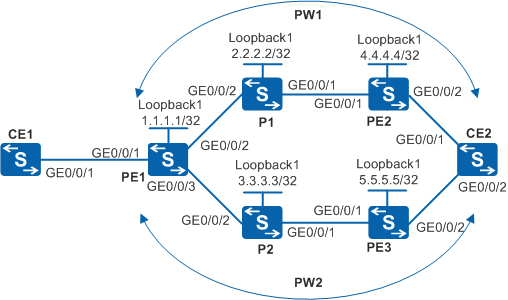
The requirements for the small-scale MPLS L2VPN are as follows:
Create PW1 (active PW) between PE1 and PE2.
Create PW2 (standby PW) between PE1 and PE3.
As shown in Figure 1, BFD is used to check connectivity of the active and standby PWs. If the active PW is faulty, services can be switched to the standby PW.

In this scenario, to avoid loops, ensure that all connected interfaces have STP disabled and connected interfaces are removed from VLAN 1. If STP is enabled and VLANIF interfaces of switches are used to construct a Layer 3 ring network, an interface on the network will be blocked. As a result, Layer 3 services on the network cannot run normally.
By default, LNP is enabled globally on the device. If a VLANIF interface is used as an AC-side interface for L2VPN, the configuration conflicts with LNP. In this case, run the lnp disable command in the system view to disable LNP.
The lnp disable command has no impact on services before the device restarts. After the device restarts, the device can only forward packets from the VLANs specified by the port default vlan command at Layer 2. The port default vlan 1 command is configured by default, so only packets of VLAN 1 can be forwarded at Layer 2.
Switch |
Interface |
VLANIF Interface |
IP Address |
|---|---|---|---|
PE1 |
GE0/0/1 |
VLANIF10 |
- |
PE1 |
GE0/0/2 |
VLANIF20 |
100.1.1.1/30 |
PE1 |
GE0/0/3 |
VLANIF30 |
200.1.1.1/30 |
PE2 |
GE0/0/1 |
VLANIF40 |
100.2.1.2/30 |
PE2 |
GE0/0/2 |
VLANIF50 |
- |
PE3 |
GE0/0/1 |
VLANIF60 |
200.2.1.2/30 |
PE3 |
GE0/0/2 |
VLANIF70 |
- |
P1 |
GE0/0/1 |
VLANIF40 |
100.2.1.1/30 |
P1 |
GE0/0/2 |
VLANIF20 |
100.1.1.2/30 |
P2 |
GE0/0/1 |
VLANIF60 |
200.2.1.1/30 |
P2 |
GE0/0/2 |
VLANIF30 |
200.1.1.2/30 |
CE1 |
GE0/0/1 |
VLANIF10 |
10.1.1.1/30 10.1.2.1/30(sub) |
CE2 |
GE0/0/1 |
VLANIF50 |
10.1.1.2/30 |
CE2 |
GE0/0/2 |
VLANIF70 |
10.1.2.2/30 |
Configuration Roadmap
Static BFD applies to small-scale networks because the static BFD configuration is fixed. The configuration roadmap is as follows:
Configure the MPLS network to make the network layer reachable.
On the AC interface of PE1, configure PW1 (from PE1 to PE2) and PW2 (from PE1 to PE3). PW1 functions as the active PW and PW2 functions as the standby PW.
Configure BFD sessions to check connectivity of PW1 and PW2.
Procedure
- Configure VLANs that each interface belongs to and assign an IP address to each VLANIF interface according to Figure 1.
# Configure CE1. The configuration on PE1, PE2, PE3, P1, P2, and CE2 is similar to the CE1, and is not mentioned here.
<HUAWEI> system-view
[HUAWEI] sysname CE1
[CE1] vlan batch 10
[CE1] interface vlanif 10
[CE1-Vlanif10] ip address 10.1.1.1 255.255.255.252
[CE1-Vlanif10] ip address 10.1.2.1 255.255.255.252 sub
[CE1-Vlanif10] quit
[CE1] interface gigabitethernet 0/0/1
[CE1-GigabitEthernet0/0/1] port link-type trunk
[CE1-GigabitEthernet0/0/1] port trunk allow-pass vlan 10
[CE1-GigabitEthernet0/0/1] quit
- Configure an IGP protocol on the MPLS backbone network so that PEs and Ps can communicate with each other.
When configuring OSPF, advertise 32-bit addresses of loopback interfaces on PE1, PE2, and PE3.
# Configure PE1. The configuration on PE2, PE3, P1, and P2 is similar to the PE1, and is not mentioned here.
[PE1] interface loopback 1
[PE1-LoopBack1] ip address 1.1.1.1 255.255.255.255
[PE1-LoopBack1] quit
[PE1] ospf 1
[PE1-ospf-1] area 0
[PE1-ospf-1-area-0.0.0.0] network 1.1.1.1 0.0.0.0
[PE1-ospf-1-area-0.0.0.0] network 100.1.1.0 0.0.0.3
[PE1-ospf-1-area-0.0.0.0] network 200.1.1.0 0.0.0.3
[PE1-ospf-1-area-0.0.0.0] quit
[PE1-ospf-1] quit
After the configuration is complete, run the display ip routing-table command on PEs. You can see that PE1 and PE2, and PE1 and PE3 have learned the routes on Loopback1 interfaces of each other.
- Configure basic MPLS functions on the MPLS backbone network.
Enable MPLS, and specify the LSR-ID as the IP address of Loopback1 interface. Enable MPLS and MPLS LDP on interfaces connecting the backbone network.
# Configure PE1. The configuration on P1, P2, PE2, and PE3 is similar to the PE1, and is not mentioned here.
[PE1] mpls lsr-id 1.1.1.1
[PE1] mpls
[PE1-mpls] quit
[PE1] mpls ldp
[PE1-mpls-ldp] quit
[PE1] interface vlanif 20
[PE1-Vlanif20] mpls
[PE1-Vlanif20] mpls ldp
[PE1-Vlanif20] quit
[PE1] interface vlanif 30
[PE1-Vlanif30] mpls
[PE1-Vlanif30] mpls ldp
[PE1-Vlanif30] quit
After the configuration is complete, run the display tunnel-info all command on PEs. You can see that MPLS LSPs are set up between PE1 and PE2, and between PE1 and PE3.
Run the display mpls ldp session command on PEs. You can see that the LDP peer relationship between the PE and the neighboring P is in Operational state.
The display on PE1 is used as an example.
[PE1] display mpls ldp session

 LDP Session(s) in Public Network
 Codes: LAM(Label Advertisement Mode), SsnAge Unit(DDDD:HH:MM)
 A '*' before a session means the session is being deleted.
 ------------------------------------------------------------------------------
 PeerID             Status      LAM  SsnRole  SsnAge      KASent/Rcv
 ------------------------------------------------------------------------------
 2.2.2.2:0        Operational   DU   Passive  0000:00:03  16/16
 3.3.3.3:0        Operational   DU   Passive  0000:00:03  13/13
 ------------------------------------------------------------------------------
 TOTAL: 2 session(s) Found.
- Establish a remote LDP session between PEs.
# Use the loopback interface address of the LDP remote peer to establish a remote LDP session.
If PEs are directly connected, you do not need to manually configure remote LDP sessions between them.
# Configure PE1.
[PE1] mpls ldp remote-peer 4.4.4.4
[PE1-mpls-ldp-remote-4.4.4.4] remote-ip 4.4.4.4
[PE1-mpls-ldp-remote-4.4.4.4] quit
[PE1] mpls ldp remote-peer 5.5.5.5
[PE1-mpls-ldp-remote-5.5.5.5] remote-ip 5.5.5.5
[PE1-mpls-ldp-remote-5.5.5.5] quit
# Configure PE2.
[PE2] mpls ldp remote-peer 1.1.1.1
[PE2-mpls-ldp-remote-1.1.1.1] remote-ip 1.1.1.1
[PE2-mpls-ldp-remote-1.1.1.1] quit
# Configure PE3.
[PE3] mpls ldp remote-peer 1.1.1.1
[PE3-mpls-ldp-remote-1.1.1.1] remote-ip 1.1.1.1
[PE3-mpls-ldp-remote-1.1.1.1] quit
After the configuration is complete, run the display mpls ldp session command on PEs. You can see that the LDP peer relationship is in Operational state, indicating that the LDP sessions are set up.
The display on PE1 is used as an example.
[PE1] display mpls ldp session

 LDP Session(s) in Public Network
 Codes: LAM(Label Advertisement Mode), SsnAge Unit(DDDD:HH:MM)
 A '*' before a session means the session is being deleted.
 ------------------------------------------------------------------------------
 PeerID             Status      LAM  SsnRole  SsnAge      KASent/Rcv
 ------------------------------------------------------------------------------
 2.2.2.2:0          Operational DU   Passive  000:00:06   27/27
 3.3.3.3:0          Operational DU   Passive  000:00:05   24/24
 4.4.4.4:0          Operational DU   Passive  000:00:00   3/3
 5.5.5.5:0          Operational DU   Passive  000:00:00   2/2
 ------------------------------------------------------------------------------
 TOTAL: 4 session(s) Found.
- Configure PWs on PEs by using PW templates.
# Configure PE1.In this example, a VLANIF interface is used as the AC-side interface, so you need to run the lnp disable command in the system view before performing the following steps. If you cannot disable LNP on the live network, do not use a VLANIF interface as the AC-side interface.
[PE1] mpls l2vpn
[PE1-l2vpn] quit
[PE1] pw-template 1to2
[PE1-pw-template-1to2] peer-address 4.4.4.4
[PE1-pw-template-1to2] control-word
[PE1-pw-template-1to2] quit
[PE1] pw-template 1to3
[PE1-pw-template-1to3] peer-address 5.5.5.5
[PE1-pw-template-1to3] control-word
[PE1-pw-template-1to3] quit
[PE1] interface vlanif 10
[PE1-Vlanif10] mpls l2vc pw-template 1to2 100
[PE1-Vlanif10] mpls l2vc pw-template 1to3 200 secondary
[PE1-Vlanif10] quit
# Configure PE2.In this example, a VLANIF interface is used as the AC-side interface, so you need to run the lnp disable command in the system view before performing the following steps. If you cannot disable LNP on the live network, do not use a VLANIF interface as the AC-side interface.
[PE2] mpls l2vpn
[PE2-l2vpn] quit
[PE2] pw-template 2to1
[PE2-pw-template-2to1] peer 1.1.1.1
[PE2-pw-template-2to1] control-word
[PE2-pw-template-2to1] quit
[PE2] interface vlanif 50
[PE2-Vlanif50] mpls l2vc pw-template 2to1 100
[PE2-Vlanif50] quit
# Configure PE3.In this example, a VLANIF interface is used as the AC-side interface, so you need to run the lnp disable command in the system view before performing the following steps. If you cannot disable LNP on the live network, do not use a VLANIF interface as the AC-side interface.
[PE3] mpls l2vpn
[PE3-l2vpn] quit
[PE3] pw-template 3to1
[PE3-pw-template-3to1] peer 1.1.1.1
[PE3-pw-template-3to1] control-word
[PE3-pw-template-3to1] quit
[PE3] interface vlanif 70
[PE3-Vlanif70] mpls l2vc pw-template 3to1 200
[PE3-Vlanif70] quit
After the configuration is complete, run the display mpls l2vc interface command on PEs. You can see that PWs are set up and are in Active state. In addition, BFD for PWs is disabled on PWs.
The display on PE1 is used as an example.
[PE1] display mpls l2vc interface vlanif 10
 *client interface       : Vlanif10 is up
  Administrator PW       : no
  session state          : up
  AC status              : up
  Ignore AC state        : disable
  VC state               : up
  Label state            : 0
  Token state            : 0
  VC ID                  : 100
  VC type                : VLAN
  destination            : 4.4.4.4
  local group ID         : 0            remote group ID      : 0
  local VC label         : 8195        remote VC label      : 8195
  local AC OAM State     : up
  local PSN OAM State    : up
  local forwarding state : forwarding
  local status code      : 0x0
  remote AC OAM state    : up
  remote PSN OAM state   : up
  remote forwarding state: forwarding
  remote status code     : 0x0
  ignore standby state   : no
  BFD for PW             : unavailable
  VCCV State             : up
  manual fault           : not set
  active state           : active
  forwarding entry       : exist
  link state             : up
  local VC MTU           : 1500         remote VC MTU        : 1500
  local VCCV             : cw alert ttl lsp-ping bfd
  remote VCCV            : cw alert ttl lsp-ping bfd
  local control word     : enable       remote control word  : enable
  tunnel policy name     : --
  PW template name       : 1to2
  primary or secondary   : primary
  load balance type      : flow
  Access-port            : false
  Switchover Flag        : false
  VC tunnel/token info   : 1 tunnels/tokens
    NO.0  TNL type         : lsp   , TNL ID : 0x48002004
    Backup TNL type        : lsp   , TNL ID : 0x0
  create time            : 0 days, 1 hours, 22 minutes, 22 seconds
  up time                : 0 days, 1 hours, 21 minutes, 14 seconds
  last change time       : 0 days, 1 hours, 21 minutes, 14 seconds
  VC last up time        : 2010/11/24 12:31:31
  VC total up time       : 0 days, 2 hours, 12 minutes, 51 seconds
  CKey                   : 16
  NKey                   : 15
  PW redundancy mode     : frr
  AdminPw interface      : --
  AdminPw link state     : --
  Diffserv Mode          : uniform
  Service Class          : be
  Color                  : --
  DomainId               : --
  Domain Name            : --

 *client interface       : Vlanif10 is up
  Administrator PW       : no
  session state          : up
  AC status              : up
  Ignore AC state        : disable
  VC state               : up
  Label state            : 0
  Token state            : 0
  VC ID                  : 200
  VC type                : VLAN
  destination            : 5.5.5.5
  local group ID         : 0            remote group ID      : 0
  local VC label         : 8196        remote VC label      : 8195
  local AC OAM State     : up
  local PSN OAM State    : up
  local forwarding state : forwarding
  local status code      : 0x0
  remote AC OAM state    : up
  remote PSN OAM state   : up
  remote forwarding state: forwarding
  remote status code     : 0x0
  ignore standby state   : no
  BFD for PW             : unavailable
  VCCV State             : up
  manual fault           : not set
  active state           : inactive
  forwarding entry       : exist
  link state             : up
  local VC MTU           : 1500         remote VC MTU        : 1500
  local VCCV             : cw alert ttl lsp-ping bfd
  remote VCCV            : cw alert ttl lsp-ping bfd
  local control word     : enable       remote control word  : enable
  tunnel policy name     : --
  PW template name       : 1to3
  primary or secondary   : secondary
  load balance type      : flow
  Access-port            : false
  VC tunnel/token info   : 1 tunnels/tokens
    NO.0  TNL type : lsp   , TNL ID : 0x48002000
    Backup TNL type      : lsp   , TNL ID : 0x0
  create time            : 0 days, 1 hours, 22 minutes, 9 seconds
  up time                : 0 days, 1 hours, 20 minutes, 22 seconds
  last change time       : 0 days, 1 hours, 20 minutes, 22 seconds
  VC last up time        : 2010-11-24 12:33:21
  VC total up time       : 0 days, 2 hours, 12 minutes, 51 seconds
  CKey                   : 16
  NKey                   : 15
  PW redundancy mode     : frr
  AdminPw interface      : --
  AdminPw link state     : --
  Diffserv Mode          : uniform
  Service Class          : be
  Color                  : --
  DomainId               : --
  Domain Name            : --

 reroute policy          : delay 30 s, resume 10 s
 reason of last reroute  : --
 time of last reroute    : -- days, -- hours, -- minutes, -- seconds
 delay timer ID          : --           residual time :--
 resume timer ID         : --           residual time :--
When the active PW works properly, you can ping 10.1.1.2 on CE2 from the primary address of CE1. The standby PW does not work, so you cannot ping 10.1.2.2 on CE2 from the secondary address of CE1.
- Configure BFD for PWs on PEs.
The local discriminator of the local system must be the same as the remote discriminator of the remote system, and the remote discriminator of the local system must be the same as the local discriminator of the remote system. The configuration cannot be changed.
# Configure PE1.
[PE1] bfd
[PE1-bfd] quit
[PE1] bfd for pw enable
[PE1] bfd 1to2 bind pw interface vlanif 10
[PE1-bfd-lsp-session-1to2] discriminator local 12
[PE1-bfd-lsp-session-1to2] discriminator remote 21
[PE1-bfd-lsp-session-1to2] commit
[PE1-bfd-lsp-session-1to2] quit
[PE1] bfd 1to3 bind pw interface vlanif 10 secondary
[PE1-bfd-lsp-session-1to3] discriminator local 13
[PE1-bfd-lsp-session-1to3] discriminator remote 31
[PE1-bfd-lsp-session-1to3] commit
[PE1-bfd-lsp-session-1to3] quit
# Configure PE2.
[PE2] bfd
[PE2-bfd] quit
[PE2] bfd for pw enable
[PE2] bfd 2to1 bind pw interface vlanif 50
[PE2-bfd-lsp-session-2to1] discriminator local 21
[PE2-bfd-lsp-session-2to1] discriminator remote 12
[PE2-bfd-lsp-session-2to1] commit
[PE2-bfd-lsp-session-2to1] quit
# Configure PE3.
[PE3] bfd
[PE3-bfd] quit
[PE3] bfd for pw enable
[PE3] bfd 3to1 bind pw interface vlanif 70
[PE3-bfd-lsp-session-3to1] discriminator local 31
[PE3-bfd-lsp-session-3to1] discriminator remote 13
[PE3-bfd-lsp-session-3to1] commit
[PE3-bfd-lsp-session-3to1] quit
After the configuration is complete, BFD sessions are set up between PE1 and PE2, and between PE1 and PE3. Run the display bfd session all command. You can see that the BFD session status is Up.
The display on PE1 is used as an example.
[PE1] display bfd session all
--------------------------------------------------------------------------------
Local  Remote PeerIpAddr      State     Type      InterfaceName
--------------------------------------------------------------------------------
12     21     --.--.--.--      Up       S_PW(M)    Vlanif10
13     31     --.--.--.--      Up       S_PW(S)    Vlanif10
--------------------------------------------------------------------------------
     Total UP/DOWN Session Number : 2/0
Run the display bfd configuration all command. You can view the BFD configuration, and find that the Commit field is True.
[PE1] display bfd configuration all -------------------------------------------------------------------------------- CFG Name CFG Type LocalDiscr MIndex SessNum Commit AdminDown -------------------------------------------------------------------------------- 1to2 S_PW(M) 12 256 1 True False 1to3 S_PW(S) 13 257 1 True False -------------------------------------------------------------------------------- Total Commit/Uncommit CFG Number : 2/0 - Verify the configuration.
When the active PW works properly, you can ping 10.1.1.2 on CE2 from the primary address of CE1. The standby PW does not work, so you cannot ping 10.1.2.2 on CE2 from the secondary address of CE1.
# Run the display mpls l2vc interface command on PEs to view the PW status. You can see that BFD for PWs is enabled on the active and standby PWs and the BFD sessions are Up.
[PE1] display mpls l2vc interface vlanif 10
 *client interface       : Vlanif10 is up
  Administrator PW       : no
  session state          : up
  AC status              : up
  Ignore AC state        : disable
  VC state               : up
  Label state            : 0
  Token state            : 0
  VC ID                  : 100
  VC type                : VLAN
  destination            : 4.4.4.4
  local group ID         : 0            remote group ID      : 0
  local VC label         : 8195        remote VC label      : 8195
  local AC OAM State     : up
  local PSN OAM State    : up
  local forwarding state : forwarding
  local status code      : 0x0
  remote AC OAM state    : up
  remote PSN OAM state   : up
  remote forwarding state: forwarding
  remote status code     : 0x0
  ignore standby state   : no
  BFD for PW             : available
    BFD sessionIndex     : 256          BFD state : up
  VCCV State             : up
  manual fault           : not set
  active state           : active
  forwarding entry       : exist
  link state             : up
  local VC MTU           : 4470         remote VC MTU        : 4470
  local VCCV             : cw alert lsp-ping bfd
  remote VCCV            : cw alert lsp-ping bfd
  local control word     : enable       remote control word  : enable
  tunnel policy name     : --
  PW template name       : 1to2
  primary or secondary   : primary
  load balance type      : flow
  Access-port            : false
  Switchover Flag        : false
  VC tunnel/token info   : 1 tunnels/tokens
    NO.0  TNL type       : lsp   , TNL ID : 0x48002004
    Backup TNL type      : lsp   , TNL ID : 0x0
  create time            : 0 days, 1 hours, 17 minutes, 55 seconds
  up time                : 0 days, 1 hours, 16 minutes, 47 seconds
  last change time       : 0 days, 1 hours, 16 minutes, 47 seconds
  VC last up time        : 2010/11/24 12:31:31
  VC total up time       : 0 days, 2 hours, 13 minutes, 55 seconds
  CKey                   : 14
  NKey                   : 1
  PW redundancy mode     : frr
  AdminPw interface      : --
  AdminPw link state     : --
  Diffserv Mode          : uniform
  Service Class          : be
  Color                  : --
  DomainId               : --
  Domain Name            : --

 *client interface       : Vlanif10 is up
  Administrator PW       : no
  session state          : up
  AC status              : up
  Ignore AC state        : disable
  VC state               : up
  Label state            : 0
  Token state            : 0
  VC ID                  : 200
  VC type                : VLAN
  destination            : 5.5.5.5
  local group ID         : 0            remote group ID      : 0
  local VC label         : 8196        remote VC label      : 8195
  local AC OAM State     : up
  local PSN OAM State    : up
  local forwarding state : forwarding
  local status code      : 0x0
  remote AC OAM state    : up
  remote PSN OAM state   : up
  remote forwarding state: forwarding
  remote status code     : 0x0
  ignore standby state   : no
  BFD for PW             : available
    BFD sessionIndex     : 257          BFD state : up
  VCCV State             : up
  manual fault           : not set
  active state           : inactive
  forwarding entry       : exist
  link state             : up
  local VC MTU           : 1500         remote VC MTU        : 1500
  local VCCV             : cw alert lsp-ping bfd
  remote VCCV            : cw alert lsp-ping bfd
  local control word     : enable       remote control word  : enable
  tunnel policy name     : --
  PW template name       : 1to3
  primary or secondary   : secondary
  load balance type      : flow
  Access-port            : false
  VC tunnel/token info   : 1 tunnels/tokens
    NO.0  TNL type       : lsp   , TNL ID : 0x48002000
    Backup TNL type      : lsp   , TNL ID : 0x0
  create time            : 0 days, 1 hours, 17 minutes, 42 seconds
  up time                : 0 days, 1 hours, 15 minutes, 55 seconds
  last change time       : 0 days, 1 hours, 15 minutes, 55 seconds
  VC last up time        : 2010-11-24 12:33:21
  VC total up time       : 0 days, 2 hours, 13 minutes, 31 seconds
  CKey                   : 16
  NKey                   : 15
  PW redundancy mode     : frr
  AdminPw interface      : --
  AdminPw link state     : --
  Diffserv Mode          : uniform
  Service Class          : be
  Color                  : --
  DomainId               : --
  Domain Name            : --

 reroute policy          : delay 30 s, resume 10 s
 reason of last reroute  : --
 time of last reroute    : -- days, -- hours, -- minutes, -- seconds
 delay timer ID          : --           residual time :--
 resume timer ID         : --           residual time :--
Run the shutdown command on VLANIF 20 of PE1 to simulate a fault on the active PW. Then, the primary address of CE1 cannot ping 10.1.1.2 on CE2. The standby PW starts to work, so the secondary address of CE1 can ping 10.1.2.2 on CE2.
[PE1] interface vlanif 20
[PE1-Vlanif20] shutdown
[PE1-Vlanif20] quit
[CE1] ping 10.1.1.2
  PING 10.1.1.2: 56  data bytes, press CTRL_C to break
    Request time out
    Request time out
    Request time out
    Request time out
    Request time out

  --- 10.1.1.2 ping statistics ---
    5 packet(s) transmitted
    0 packet(s) received
    100.00% packet loss
[CE1] ping 10.1.2.2 PING 10.1.2.2: 56 data bytes, press CTRL_C to break Reply from 10.1.2.2: bytes=56 Sequence=1 ttl=255 time=140 ms Reply from 10.1.2.2: bytes=56 Sequence=2 ttl=255 time=160 ms Reply from 10.1.2.2: bytes=56 Sequence=3 ttl=255 time=160 ms Reply from 10.1.2.2: bytes=56 Sequence=4 ttl=255 time=160 ms Reply from 10.1.2.2: bytes=56 Sequence=5 ttl=255 time=160 ms --- 10.1.2.2 ping statistics --- 5 packet(s) transmitted 5 packet(s) received 0.00% packet loss round-trip min/avg/max = 140/156/160 ms# Run the display mpls l2vc interface command on PEs to view the PW status. The VC of the active PW is Down. The VC of the standby PW is Up, BFD for PWs is available, and the BFD session is Up.
[PE1] display mpls l2vc interface Vlanif 10
 *client interface       : Vlanif10 is up
  Administrator PW       : no
  session state          : down
  AC status              : up
  Ignore AC state        : disable
  VC state               : down
  Label state            : 0
  Token state            : 0
  VC ID                  : 100
  VC type                : VLAN
  destination            : 4.4.4.4
  local group ID         : 0            remote group ID      : 0
  local VC label         : 8195        remote VC label      : 0
  local AC OAM State     : up
  local PSN OAM State    : up
  local forwarding state : not forwarding
  local status code      : 0x1
  BFD for PW             : available
    BFD sessionIndex     : 4096         BFD state : down
  VCCV State             : up
  manual fault           : not set
  active state           : inactive
  forwarding entry       : not exist
  link state             : down
  local VC MTU           : 1500         remote VC MTU        : 0
  local VCCV             : cw alert lsp-ping bfd
  remote VCCV            : none
  local control word     : enable       remote control word  : none
  tunnel policy name     : --
  PW template name       : 1to2
  primary or secondary   : primary
  load balance type      : flow
  Access-port            : false
  Switchover Flag        : false
  VC tunnel/token info   : 0 tunnels/tokens
    Backup TNL type      : lsp   , TNL ID : 0x0
  create time            : 0 days, 0 hours, 30 minutes, 58 seconds
  up time                : 0 days, 0 hours, 0 minutes, 0 seconds
  last change time       : 0 days, 0 hours, 6 minutes, 46 seconds
  VC last up time        : 2010/11/24 12:31:31
  VC total up time       : 0 days, 2 hours, 12 minutes, 51 seconds
  CKey                   : 14
  NKey                   : 1
  PW redundancy mode     : frr
  AdminPw interface      : --
  AdminPw link state     : --
  Diffserv Mode          : uniform
  Service Class          : be
  Color                  : --
  DomainId               : --
  Domain Name            : --

 *client interface       : Vlanif10 is up
  Administrator PW       : no
  session state          : up
  AC status              : up
  Ignore AC state        : disable
  VC state               : up
  Label state            : 0
  Token state            : 0
  VC ID                  : 200
  VC type                : VLAN
  destination            : 5.5.5.5
  local group ID         : 0            remote group ID      : 0
  local VC label         : 8196        remote VC label      : 8195
  local AC OAM State     : up
  local PSN OAM State    : up
  local forwarding state : forwarding
  local status code      : 0x0
  remote AC OAM state    : up
  remote PSN OAM state   : up
  remote forwarding state: forwarding
  remote status code     : 0x0
  ignore standby state   : no
  BFD for PW             : available
    BFD sessionIndex     : 257          BFD state : up
  VCCV State             : up
  manual fault           : not set
  active state           : active
  forwarding entry       : exist
  link state             : up
  local VC MTU           : 1500         remote VC MTU        : 1500
  local VCCV             : cw alert lsp-ping bfd
  remote VCCV            : cw alert lsp-ping bfd
  local control word     : enable       remote control word  : enable
  tunnel policy name     : --
  PW template name       : 1to3
  primary or secondary   : secondary
  load balance type      : flow
  Access-port            : false
  VC tunnel/token info   : 1 tunnels/tokens
    NO.0  TNL type       : lsp   , TNL ID : 0x10028
    Backup TNL type      : lsp   , TNL ID : 0x0
  create time            : 0 days, 0 hours, 30 minutes, 58 seconds
  up time                : 0 days, 0 hours, 25 minutes, 12 seconds
  last change time       : 0 days, 0 hours, 25 minutes, 12 seconds
  VC last up time        : 2010/11/24 12:31:31
  VC total up time       : 0 days, 2 hours, 12 minutes, 51 seconds
  CKey                   : 16
  NKey                   : 15
  PW redundancy mode     : frr
  AdminPw interface      : --
  AdminPw link state     : --
  Diffserv Mode          : uniform
  Service Class          : be
  Color                  : --
  DomainId               : --
  Domain Name            : --

 reroute policy          : delay 30 s, resume 10 s
 reason of last reroute  : --
 time of last reroute    : -- days, -- hours, -- minutes, -- seconds
 delay timer ID          : --           residual time :--
 resume timer ID         : --           residual time :--
[PE1] interface vlanif 20
[PE1-Vlanif20] undo shutdown
[PE1-Vlanif20] quit
Configuration Files
CE1 configuration file
#
sysname CE1
#
vlan batch 10
#
interface Vlanif10
 ip address 10.1.1.1 255.255.255.252
 ip address 10.1.2.1 255.255.255.252 sub
#
interface GigabitEthernet0/0/1
 port link-type trunk
 port trunk allow-pass vlan 10
#
return
PE1 configuration file

The lnp disable command has no impact on services before the device restarts. After the device restarts, the device can only forward packets from the VLANs specified by the port default vlan command at Layer 2. The port default vlan 1 command is configured by default, so only packets of VLAN 1 can be forwarded at Layer 2.
#
sysname PE1
#
vlan batch 10 20 30
#
lnp disable #bfd for pw enable
#
bfd
#
mpls lsr-id 1.1.1.1
mpls
#
mpls l2vpn
#
pw-template 1to2
 peer-address 4.4.4.4
 control-word
#
pw-template 1to3
 peer-address 5.5.5.5
 control-word
#
mpls ldp
#
mpls ldp remote-peer 4.4.4.4
 remote-ip 4.4.4.4
#
mpls ldp remote-peer 5.5.5.5
 remote-ip 5.5.5.5
#
interface Vlanif10
 mpls l2vc pw-template 1to2 100
 mpls l2vc pw-template 1to3 200 secondary
#
interface Vlanif20
 ip address 100.1.1.1 255.255.255.252
 mpls
 mpls ldp
#
interface Vlanif30
 ip address 200.1.1.1 255.255.255.252
 mpls
 mpls ldp
#
interface GigabitEthernet0/0/1
 port link-type trunk
 port trunk allow-pass vlan 10
#
interface GigabitEthernet0/0/2
 port link-type trunk
 port trunk allow-pass vlan 20
#
interface GigabitEthernet0/0/3
 port link-type trunk
 port trunk allow-pass vlan 30
#
interface LoopBack1
 ip address 1.1.1.1 255.255.255.255
#
ospf 1
 area 0.0.0.0
  network 1.1.1.1 0.0.0.0
  network 100.1.1.0 0.0.0.3
  network 200.1.1.0 0.0.0.3
#
bfd 1to2 bind pw interface Vlanif10
 discriminator local 12
 discriminator remote 21
 commit
#
bfd 1to3 bind pw interface Vlanif10 secondary
 discriminator local 13
 discriminator remote 31
 commit
#
return
P1 configuration file
#
sysname P1
#
vlan batch 20 40
#
mpls lsr-id 2.2.2.2
mpls
#
mpls ldp
#
interface Vlanif20
 ip address 100.1.1.2 255.255.255.252
 mpls
 mpls ldp
#
interface Vlanif40
 ip address 100.2.1.1 255.255.255.252
 mpls
 mpls ldp
#
interface GigabitEthernet0/0/1
 port link-type trunk
 port trunk allow-pass vlan 40
#
interface GigabitEthernet0/0/2
 port link-type trunk
 port trunk allow-pass vlan 20
#
interface LoopBack1
 ip address 2.2.2.2 255.255.255.255
#
ospf 1
 area 0.0.0.0
  network 2.2.2.2 0.0.0.0
  network 100.1.1.0 0.0.0.3
  network 100.2.1.0 0.0.0.3
#
return
P2 configuration file
#
sysname P2
#
vlan batch 30 60
#
mpls lsr-id 3.3.3.3
mpls
#
mpls ldp
#
interface Vlanif30
 ip address 200.1.1.2 255.255.255.252
 mpls
 mpls ldp
#
interface Vlanif60
 ip address 200.2.1.1 255.255.255.252
 mpls
 mpls ldp
#
interface GigabitEthernet0/0/1
 port link-type trunk
 port trunk allow-pass vlan 60
#
interface GigabitEthernet0/0/2
 port link-type trunk
 port trunk allow-pass vlan 30
#
interface LoopBack1
 ip address 3.3.3.3 255.255.255.255
#
ospf 1
 area 0.0.0.0
  network 3.3.3.3 0.0.0.0
  network 200.1.1.0 0.0.0.3
  network 200.2.1.0 0.0.0.3
#
return
PE2 configuration file
The lnp disable command has no impact on services before the device restarts. After the device restarts, the device can only forward packets from the VLANs specified by the port default vlan command at Layer 2. The port default vlan 1 command is configured by default, so only packets of VLAN 1 can be forwarded at Layer 2.
#
sysname PE2
#
vlan batch 40 50
#
lnp disable #bfd for pw enable
#
bfd
#
mpls lsr-id 4.4.4.4
mpls
#
mpls l2vpn
#
pw-template 2to1
 peer-address 1.1.1.1
 control-word
#
mpls ldp
#
mpls ldp remote-peer 1.1.1.1
 remote-ip 1.1.1.1
#
interface Vlanif40
 ip address 100.2.1.2 255.255.255.252
 mpls
 mpls ldp
#
interface Vlanif50
 mpls l2vc pw-template 2to1 100
#
interface GigabitEthernet0/0/1
 port link-type trunk
 port trunk allow-pass vlan 40
#
interface GigabitEthernet0/0/2
 port link-type trunk
 port trunk allow-pass vlan 50
#
interface LoopBack1
 ip address 4.4.4.4 255.255.255.255
#
ospf 1
 area 0.0.0.0
  network 4.4.4.4 0.0.0.0
  network 100.2.1.0 0.0.0.3
#
bfd 2to1 bind pw interface Vlanif50
 discriminator local 21
 discriminator remote 12
 commit
#
return
PE3 configuration file
The lnp disable command has no impact on services before the device restarts. After the device restarts, the device can only forward packets from the VLANs specified by the port default vlan command at Layer 2. The port default vlan 1 command is configured by default, so only packets of VLAN 1 can be forwarded at Layer 2.
#
sysname PE3
#
vlan batch 60 70
#
lnp disable #bfd for pw enable
#
bfd
#
mpls lsr-id 5.5.5.5
mpls
#
mpls l2vpn
#
pw-template 3to1
 peer-address 1.1.1.1
 control-word
#
mpls ldp
#
mpls ldp remote-peer 1.1.1.1
 remote-ip 1.1.1.1
#
interface Vlanif60
 ip address 200.2.1.2 255.255.255.252
 mpls
 mpls ldp
#
interface Vlanif70
 mpls l2vc pw-template 3to1 200
#
interface GigabitEthernet0/0/1
 port link-type trunk
 port trunk allow-pass vlan 60
#
interface GigabitEthernet0/0/2
 port link-type trunk
 port trunk allow-pass vlan 70
#
interface LoopBack1
 ip address 5.5.5.5 255.255.255.255
#
ospf 1
 area 0.0.0.0
  network 5.5.5.5 0.0.0.0
  network 200.2.1.0 0.0.0.3
#
bfd 3to1 bind pw interface Vlanif70
 discriminator local 31
 discriminator remote 13
 commit
#
return
CE2 configuration file
#
sysname CE2
#
vlan batch 50 70
#
interface Vlanif50
 ip address 10.1.1.2 255.255.255.252
#
interface Vlanif70
 ip address 10.1.2.2 255.255.255.252
#
interface GigabitEthernet0/0/1
 port link-type trunk
 port trunk allow-pass vlan 50
#
interface GigabitEthernet0/0/2
 port link-type trunk
 port trunk allow-pass vlan 70
#
return