Example for Configuring Dynamic BFD for a Single-hop PW
Networking Requirements
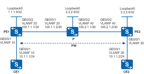
As shown in Figure 1, PE1, P, and PE2 are on the same MPLS network. The configurations of Ps on the network are similar. A single-hop PW is established between PE1 and PE2. It is required that a BFD session be established to detect connectivity of the PW to protect services on the PW.

By default, LNP is enabled globally on the device. If a VLANIF interface is used as an AC-side interface for L2VPN, the configuration conflicts with LNP. In this case, run the lnp disable command in the system view to disable LNP.
The lnp disable command has no impact on services before the device restarts. After the device restarts, the device can only forward packets from the VLANs specified by the port default vlan command at Layer 2. The port default vlan 1 command is configured by default, so only packets of VLAN 1 can be forwarded at Layer 2.
Configuration Roadmap
When configuring dynamic BFD for LDP LSPs, you do not need to specify BFD parameters. Dynamic BFD improves fault detection and reduces configuration workload. Dynamic BFD applies to large-scale networks. The configuration roadmap is as follows:
Establish a single-hop PW between CE1 and CE2.
Enable MPLS L2VPN and create VCs on PE1 and PE2.
Configure basic BFD functions and dynamic BFD for PWs on PEs.
Procedure
- Configure VLANs that each interface belongs to and assign an IP address to each VLANIF interface according to Figure 1.
# Configure CE1. The configuration on PE1, PE2, and P is similar to the CE1, and is not mentioned here.
<HUAWEI> system-view
[HUAWEI] sysname CE1
[CE1] vlan batch 10
[CE1] interface vlanif 10
[CE1-Vlanif10] ip address 10.1.1.1 255.255.255.0
[CE1-Vlanif10] quit
[CE1] interface gigabitethernet 0/0/1
[CE1-GigabitEthernet0/0/1] port link-type trunk
[CE1-GigabitEthernet0/0/1] port trunk allow-pass vlan 10
[CE1-GigabitEthernet0/0/1] quit
- Configure an IGP protocol on the MPLS backbone network.
Configure an IGP on the MPLS backbone network. This example uses OSPF.
# Configure PE1.
[PE1] interface loopback 0
[PE1-LoopBack0] ip address 1.1.1.9 32
[PE1-LoopBack0] quit
[PE1] interface vlanif 20
[PE1-Vlanif20] ip address 100.1.1.1 30
[PE1-Vlanif20] quit
[PE1] ospf 1
[PE1-ospf-1] area 0
[PE1-ospf-1-area-0.0.0.0] network 1.1.1.9 0.0.0.0
[PE1-ospf-1-area-0.0.0.0] network 100.1.1.0 0.0.0.3
[PE1-ospf-1-area-0.0.0.0] quit
[PE1-ospf-1] quit
# Configure P.
[P] interface loopback 0
[P-LoopBack0] ip address 2.2.2.9 32
[P-LoopBack0] quit
[P] interface vlanif 20
[P-Vlanif20] ip address 100.1.1.2 30
[P-Vlanif20] quit
[P] interface vlanif 40
[P-Vlanif40] ip address 100.2.1.1 30
[P-Vlanif40] quit
[P] ospf 1
[P-ospf-1] area 0
[P-ospf-1-area-0.0.0.0] network 2.2.2.9 0.0.0.0
[P-ospf-1-area-0.0.0.0] network 100.1.1.0 0.0.0.3
[P-ospf-1-area-0.0.0.0] network 100.2.1.0 0.0.0.3
[P-ospf-1-area-0.0.0.0] quit
[P-ospf-1] quit
# Configure PE2.
[PE2] interface loopback 0
[PE2-LoopBack0] ip address 3.3.3.9 32
[PE2-LoopBack0] quit
[PE2] interface vlanif 40
[PE2-Vlanif40] ip address 100.2.1.2 30
[PE2-Vlanif40] quit
[PE2] ospf 1
[PE2-ospf-1] area 0
[PE2-ospf-1-area-0.0.0.0] network 3.3.3.9 0.0.0.0
[PE2-ospf-1-area-0.0.0.0] network 100.2.1.0 0.0.0.3
[PE2-ospf-1-area-0.0.0.0] quit
[PE2-ospf-1] quit
After the configuration is complete, run the display ip routing-table command on PEs. You can see that PE1 and PE2 have learned the routes on Loopback1 interfaces of each other.
- Configure basic MPLS functions on the MPLS backbone network.
# Enable MPLS, and specify the LSR-ID as the IP address of Loopback1 interface. Enable MPLS and MPLS LDP on interfaces connecting the backbone network.
# Configure PE1.
[PE1] mpls lsr-id 1.1.1.9
[PE1] mpls
[PE1-mpls] quit
[PE1] mpls ldp
[PE1-mpls-ldp] quit
[PE1] interface vlanif 20
[PE1-Vlanif20] mpls
[PE1-Vlanif20] mpls ldp
[PE1-Vlanif20] quit
# Configure P.
[P] mpls lsr-id 2.2.2.9
[P] mpls
[P-mpls] quit
[P] mpls ldp
[P-mpls-ldp] quit
[P] interface vlanif 20
[P-Vlanif20] mpls
[P-Vlanif20] mpls ldp
[P-Vlanif20] quit
[P] interface vlanif 40
[P-Vlanif40] mpls
[P-Vlanif40] mpls ldp
[P-Vlanif40] quit
# Configure PE2.
[PE2] mpls lsr-id 3.3.3.9
[PE2] mpls
[PE2-mpls] quit
[PE2] mpls ldp
[PE2-mpls-ldp] quit
[PE2] interface vlanif 40
[PE2-Vlanif40] mpls
[PE2-Vlanif40] mpls ldp
[PE2-Vlanif40] quit
After the configuration is complete, run the display tunnel-info all command on PEs. You can see that MPLS LSPs are set up between PE1 and PE2.
The display on PE1 is used as an example.
[PE1] display tunnel-info all
* -> Allocated VC Token
Tunnel ID           Type                 Destination           Token
----------------------------------------------------------------------
0x89                lsp                   2.2.2.9                137
0x8a                lsp                   2.2.2.9                138
0x8b                lsp                   3.3.3.9                139
0x8c                lsp                   3.3.3.9                140
Run the display mpls ldp session command on PE. You can see that the LDP peer relationship between the PE and the neighboring P is in Operational state.
The display on PE1 is used as an example.
[PE1] display mpls ldp session

 LDP Session(s) in Public Network
 Codes: LAM(Label Advertisement Mode), SsnAge Unit(DDDD:HH:MM)
 A '*' before a session means the session is being deleted.
 ------------------------------------------------------------------------------
 PeerID             Status      LAM  SsnRole  SsnAge      KASent/Rcv
 ------------------------------------------------------------------------------
 2.2.2.9:0          Operational DU   Passive  0000:00:02  10/10
 ------------------------------------------------------------------------------
 TOTAL: 1 session(s) Found.
- Establish a remote LDP session between PEs.
# Use the loopback interface address of the LDP remote peer to establish a remote LDP session.
If PEs are directly connected, you do not need to manually configure remote LDP sessions between them.
# Configure PE1.
[PE1] mpls ldp remote-peer 3.3.3.9
[PE1-mpls-ldp-remote-3.3.3.9] remote-ip 3.3.3.9
[PE1-mpls-ldp-remote-3.3.3.9] quit
# Configure PE2.
[PE2] mpls ldp remote-peer 1.1.1.9
[PE2-mpls-ldp-remote-1.1.1.9] remote-ip 1.1.1.9
[PE2-mpls-ldp-remote-1.1.1.9] quit
After the configuration is complete, run the display mpls ldp session command on PEs. You can see that the LDP peer relationship is in Operational state, indicating that the LDP sessions are set up.
The display on PE1 is used as an example.
[PE1] display mpls ldp session

 LDP Session(s) in Public Network
 Codes: LAM(Label Advertisement Mode), SsnAge Unit(DDDD:HH:MM)
 A '*' before a session means the session is being deleted.
 ------------------------------------------------------------------------------
 PeerID             Status      LAM  SsnRole  SsnAge      KASent/Rcv
 ------------------------------------------------------------------------------
 2.2.2.9:0          Operational DU   Passive  0000:00:03  16/16
 3.3.3.9:0          Operational DU   Passive  0000:00:00  2/2
 ------------------------------------------------------------------------------
 TOTAL: 2 session(s) Found.
- Configure PWs on PEs by using PW templates.
# Configure PE1.In this example, a VLANIF interface is used as the AC-side interface, so you need to run the lnp disable command in the system view before performing the following steps. If you cannot disable LNP on the live network, do not use a VLANIF interface as the AC-side interface.
[PE1] mpls l2vpn
[PE1-l2vpn] quit
[PE1] pw-template 1to2
[PE1-pw-template-1to2] peer-address 3.3.3.9
[PE1-pw-template-1to2] control-word
[PE1-pw-template-1to2] quit
[PE1] interface vlanif 10
[PE1-Vlanif10] mpls l2vc pw-template 1to2 100
[PE1-Vlanif10] quit
# Configure PE2.In this example, a VLANIF interface is used as the AC-side interface, so you need to run the lnp disable command in the system view before performing the following steps. If you cannot disable LNP on the live network, do not use a VLANIF interface as the AC-side interface.
[PE2] mpls l2vpn
[PE2-l2vpn] quit
[PE2] pw-template 2to1
[PE2-pw-template-2to1] peer 1.1.1.9
[PE2-pw-template-2to1] control-word
[PE2-pw-template-2to1] quit
[PE2] interface vlanif 30
[PE2-Vlanif30] mpls l2vc pw-template 2to1 100
[PE2-Vlanif30] quit
After the configuration is complete, run the display mpls l2vc interface command on PEs. You can see that PWs are set up and are in Active state. In addition, BFD for PWs is disabled on the PWs.
The display on PE1 is used as an example.
[PE1] display mpls l2vc interface vlanif 10
 *client interface       : Vlanif10 is up
  Administrator PW       : no
  session state          : up
  AC status              : up
  Ignore AC state        : disable
  VC state               : up
  Label state            : 0
  Token state            : 0
  VC ID                  : 100
  VC type                : VLAN
  destination            : 3.3.3.9
  local group ID         : 0            remote group ID      : 0
  local VC label         : 8195         remote VC label      : 8195
  local AC OAM State     : up
  local PSN OAM State    : up
  local forwarding state : forwarding
  local status code      : 0x0
  remote AC OAM state    : up
  remote PSN OAM state   : up
  remote forwarding state: forwarding
  remote status code     : 0x0
  ignore standby state   : no
  BFD for PW             : unavailable
  VCCV State             : up
  manual fault           : not set
  active state           : active
  forwarding entry       : exist
  link state             : up
  local VC MTU           : 1500         remote VC MTU        : 1500
  local VCCV             : cw alert ttl lsp-ping bfd
  remote VCCV            : cw alert ttl lsp-ping bfd
  local control word     : enable       remote control word  : enable
  tunnel policy name     : --
  PW template name       : 1to2
  primary or secondary   : primary
  load balance type      : flow
  Access-port            : false
  Switchover Flag        : false
  VC tunnel/token info   : 1 tunnels/tokens
    NO.0  TNL type       : lsp   , TNL ID : 0x8b
    Backup TNL type      : lsp   , TNL ID : 0x0
  create time            : 0 days, 0 hours, 2 minutes, 9 seconds
  up time                : 0 days, 0 hours, 1 minutes, 9 seconds
  last change time       : 0 days, 0 hours, 1 minutes, 9 seconds
  VC last up time        : 2010/11/24 14:31:31
  VC total up time       : 0 days, 2 hours, 12 minutes, 51 seconds
  CKey                   : 16
  NKey                   : 15
  PW redundancy mode     : --
  AdminPw interface      : --
  AdminPw link state     : --
  Diffserv Mode          : uniform
  Service Class          : --
  Color                  : --
  DomainId               : --
  Domain Name            : --
- Configure dynamic BFD for PWs on PEs.
# Configure PE1.
[PE1] bfd
[PE1-bfd] quit
[PE1] bfd for pw enable
[PE1] interface vlanif 10
[PE1-Vlanif10] mpls l2vpn pw bfd min-rx-interval 100 min-tx-interval 100
[PE1-Vlanif10] quit
# Configure PE2.
[PE2] bfd
[PE2-bfd] quit
[PE2] bfd for pw enable
[PE2] interface vlanif 30
[PE2-Vlanif30] mpls l2vpn pw bfd min-rx-interval 100 min-tx-interval 100
[PE2-Vlanif30] quit
- Verify the configuration.
# CE1 and CE2 can ping each other successfully.
<CE1> ping 10.1.1.2
  PING 10.1.1.2: 56  data bytes, press CTRL_C to break
    Reply from 10.1.1.2: bytes=56 Sequence=1 ttl=255 time=360 ms
    Reply from 10.1.1.2: bytes=56 Sequence=2 ttl=255 time=60 ms
    Reply from 10.1.1.2: bytes=56 Sequence=3 ttl=255 time=160 ms
    Reply from 10.1.1.2: bytes=56 Sequence=4 ttl=255 time=90 ms
    Reply from 10.1.1.2: bytes=56 Sequence=5 ttl=255 time=160 ms

  --- 10.1.1.2 ping statistics ---
    5 packet(s) transmitted
    5 packet(s) received
    0.00% packet loss
    round-trip min/avg/max = 60/166/360 ms
# Run the display mpls l2vc interface command on PEs to view the PW status. You can see that BFD for PWs is enabled and the BFD session is Up.
The display on PE1 is used as an example.
[PE1] display mpls l2vc interface vlanif 10
 *client interface       : Vlanif10 is up
  Administrator PW       : no
  session state          : up
  AC status              : up
  Ignore AC state        : disable
  VC state               : up
  Label state            : 0
  Token state            : 0
  VC ID                  : 100
  VC type                : VLAN
  destination            : 3.3.3.9
  local group ID         : 0            remote group ID      : 0
  local VC label         : 8195         remote VC label      : 8195
  local AC OAM State     : up
  local PSN OAM State    : up
  local forwarding state : forwarding
  local status code      : 0x0
  remote AC OAM state    : up
  remote PSN OAM state   : up
  remote forwarding state: forwarding
  remote status code     : 0x0
  ignore standby state   : no
  Dynamic BFD for PW     : enable
  Detect Multipier       : 3
  Min Transit Interval   : 100
  Max Receive Interval   : 100
  Dynamic BFD Session    : built
  BFD for PW             : available
    BFD sessionIndex     : 256          BFD state : up
  VCCV State             : up
  manual fault           : not set
  active state           : active
  forwarding entry       : exist
  link state             : up
  local VC MTU           : 4470         remote VC MTU        : 4470
  local VCCV             : cw alert ttl lsp-ping bfd
  remote VCCV            : cw alert ttl lsp-ping bfd
  local control word     : enable       remote control word  : enable
  tunnel policy name     : --
  PW template name       : 1to2
  primary or secondary   : primary
  load balance type      : flow
  Access-port            : false
  Switchover Flag        : false
  VC tunnel/token info   : 1 tunnels/tokens
    NO.0  TNL type       : lsp   , TNL ID : 0x8b
    Backup TNL type      : lsp   , TNL ID : 0x0
  create time            : 0 days, 0 hours, 6 minutes, 43 seconds
  up time                : 0 days, 0 hours, 5 minutes, 43 seconds
  last change time       : 0 days, 0 hours, 5 minutes, 43 seconds
  VC last up time        : 2010-11-24 14:33:31
  VC total up time       : 0 days, 2 hours, 11 minutes, 55 seconds
  CKey                   : 16
  NKey                   : 15
  PW redundancy mode     : --
  AdminPw interface      : --
  AdminPw link state     : --
  Diffserv Mode          : uniform
  Service Class          : --
  Color                  : --
  DomainId               : --
  Domain Name            : --
# Run the display bfd session all verbose command on PEs to view the BFD session status. You can see that the BFD session is Up, the BFD session is bound to a PW, and the type of the BFD session is dynamic.
The display on PE1 is used as an example.
[PE1] display bfd session all verbose
--------------------------------------------------------------------------------
Session MIndex : 256          State : Up           Name : dyn_8192
--------------------------------------------------------------------------------
Local Discriminator    : 8192             Remote Discriminator   : 8192
Session Detect Mode    : Asynchronous Mode Without Echo Function
BFD Bind Type          : PW(Master)
Bind Session Type      : Dynamic
Bind Peer IP Address   : -.-.-.-
NextHop Ip Address     : -.-.-.-
Bind Interface         : Vlanif10
PW TTL Mode            : -                PW TTL                 : -
Node                   : UPE
Encapsulation Type     : -                Vc Id                  : -
Track Interface        : -
Local Vc Label         : 1026             Remote Vc Label        : 1026
Swap Vc Label          : -
FSM Board Id           : 0                TOS-EXP                : 7
Min Tx Interval (ms)   : 100              Min Rx Interval (ms)   : 100
Actual Tx Interval (ms): 100              Actual Rx Interval (ms): 100
Local Detect Multi     : 3                Detect Interval (ms)   : 300
Echo Passive           : Disable          Acl Number             : -
Destination Port       : 3784             TTL                    : 1
Proc Interface Status  : Disable          Process PST            : Enable
WTR Interval (ms)      : -
Active Multi           : 3                DSCP                   : -
Last Local Diagnostic  : No Diagnostic
Bind Application       : L2VPN | OAM_MANAGER | MPLSFW
Session TX TmrID       : -                Session Detect TmrID   : -
Session Init TmrID     : -                Session WTR TmrID      : -
Session Echo Tx TmrID  : -
PDT Index              : FSM-0 | RCV-0 | IF-0 | TOKEN-0
Session Description    : -
--------------------------------------------------------------------------------

Total UP/DOWN Session Number : 1/0
Configuration Files
CE1 configuration file
#
sysname CE1
#
vlan batch 10
#
interface Vlanif10
 ip address 10.1.1.1 255.255.255.0
#
interface GigabitEthernet0/0/1
 port link-type trunk
 port trunk allow-pass vlan 10
#
return
PE1 configuration file

The lnp disable command has no impact on services before the device restarts. After the device restarts, the device can only forward packets from the VLANs specified by the port default vlan command at Layer 2. The port default vlan 1 command is configured by default, so only packets of VLAN 1 can be forwarded at Layer 2.
#
sysname PE1
#
vlan batch 10 20
#
lnp disable #bfd for pw enable
#
bfd
#
mpls lsr-id 1.1.1.9
mpls
#
mpls l2vpn
#
pw-template 1to2
 peer-address 3.3.3.9
 control-word
#
mpls ldp
#
mpls ldp remote-peer 3.3.3.9
 remote-ip 3.3.3.9
#
interface Vlanif10
 mpls l2vc pw-template 1to2 100
 mpls l2vpn pw bfd min-rx-interval 100 min-tx-interval 100
#
interface Vlanif20
 ip address 100.1.1.1 255.255.255.252
 mpls
 mpls ldp
#
interface GigabitEthernet0/0/1
 port link-type trunk
 port trunk allow-pass vlan 10
#
interface GigabitEthernet0/0/2
 port link-type trunk
 port trunk allow-pass vlan 20
#
interface LoopBack0
 ip address 1.1.1.9 255.255.255.255
#
ospf 1
 area 0.0.0.0
  network 1.1.1.9 0.0.0.0
  network 100.1.1.0 0.0.0.3
#
return
P configuration file
#
sysname P
#
vlan batch 20 40
#
mpls lsr-id 2.2.2.9
mpls
#
mpls ldp
#
interface Vlanif20
 ip address 100.1.1.2 255.255.255.252
 mpls
 mpls ldp
#
interface Vlanif40
 ip address 100.2.1.1 255.255.255.252
 mpls
 mpls ldp
#
interface GigabitEthernet0/0/1
 port link-type trunk
 port trunk allow-pass vlan 20
#
interface GigabitEthernet0/0/2
 port link-type trunk
 port trunk allow-pass vlan 40
#
interface LoopBack0
 ip address 2.2.2.9 255.255.255.255
#
ospf 1
 area 0.0.0.0
  network 2.2.2.9 0.0.0.0
  network 100.1.1.0 0.0.0.3
  network 100.2.1.0 0.0.0.3
#
return
PE2 configuration file
The lnp disable command has no impact on services before the device restarts. After the device restarts, the device can only forward packets from the VLANs specified by the port default vlan command at Layer 2. The port default vlan 1 command is configured by default, so only packets of VLAN 1 can be forwarded at Layer 2.
#
sysname PE2
#
vlan batch 30 40
#
lnp disable #bfd for pw enable
#
bfd
#
mpls lsr-id 3.3.3.9
mpls
#
mpls l2vpn
#
pw-template 2to1
 peer-address 1.1.1.9
 control-word
#
mpls ldp
#
mpls ldp remote-peer 1.1.1.9
 remote-ip 1.1.1.9
#
interface Vlanif30
 mpls l2vc pw-template 2to1 100
 mpls l2vpn pw bfd min-rx-interval 100 min-tx-interval 100
#
interface Vlanif40
 ip address 100.2.1.2 255.255.255.252
 mpls
 mpls ldp
#
interface GigabitEthernet0/0/1
 port link-type trunk
 port trunk allow-pass vlan 30
#
interface GigabitEthernet0/0/2
 port link-type trunk
 port trunk allow-pass vlan 40
#
interface LoopBack0
 ip address 3.3.3.9 255.255.255.255
#
ospf 1
 area 0.0.0.0
  network 3.3.3.9 0.0.0.0
  network 100.2.1.0 0.0.0.3
#
return
CE2 configuration file
#
sysname CE2
#
vlan batch 30
#
interface Vlanif30
 ip address 10.1.1.2 255.255.255.0
#
interface GigabitEthernet0/0/1
 port link-type trunk
 port trunk allow-pass vlan 30
#
return