Example for Configuring PW Redundancy in a Scenario Where CEs Are Asymmetrically Connected to PEs
Networking Requirements
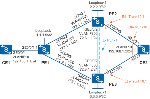
As shown in Figure 1, CE1 and CE2 belong to the same enterprise network. CE1 is single-homed to PE1, and CE2 is dual-homed to PE2 and PE3 over Eth-Trunks. The PWs between PE1 and PE2 and between PE1 and PE3 work in PW redundancy mode to ensure reliable communication between CE1 and CE2. BFD is configured to quickly detect link faults on the public network and trigger rapid PW switchovers.

In this scenario, to avoid loops, ensure that all connected interfaces have STP disabled and connected interfaces are removed from VLAN 1. If STP is enabled and VLANIF interfaces of switches are used to construct a Layer 3 ring network, an interface on the network will be blocked. As a result, Layer 3 services on the network cannot run normally.
By default, link type negotiation is enabled globally. If L2VPN uses a VLANIF interface as the AC interface, you must run the lnp disable command in the system view to disable link type negotiation first.
The CEs have the same VLAN configured; otherwise, they cannot communicate with each other.
Configuration Roadmap
The configuration roadmap is as follows:
Configure an IGP on the backbone network to transmit data packets between the PEs.
Configure basic MPLS functions and LDP on devices on the backbone network because implementation of PWE3 relies on basic MPLS functions.
Configure PW redundancy for service PWs and mPWs to ensure reliable communication between CE1 and CE2.
Configure BFD to quickly detect link faults on the backbone network and implement rapid PW switchovers. The configurations include configuring BFD for mPW and associating service PWs with the mPWs.
Configure an E-Trunk and negotiate the primary/secondary status of the PWs. Bind the E-Trunk with BFD to accelerate fault detection on AC-side links.
Procedure
- Assign IP addresses to interfaces.
Add each interface on the devices to a VLAN and assign an IP address to each interface.
# Configure CE1. The configuration on PE1, PE2, PE3, and CE2 is similar to the CE1, and is not mentioned here.
<HUAWEI> system-view
[HUAWEI] sysname CE1
[CE1] vlan 10
[CE1-vlan10] quit
[CE1] interface vlanif 10
[CE1-Vlanif10] ip address 192.168.1.1 255.255.255.0
[CE1-Vlanif10] quit
[CE1] interface gigabitethernet 0/0/1
[CE1-GigabitEthernet0/0/1] port link-type trunk
[CE1-GigabitEthernet0/0/1] port trunk allow-pass vlan 10
[CE1-GigabitEthernet0/0/1] quit
- Configure an IGP. In this example, OSPF is used.
Configure OSPF on the PEs.
# Configure PE1. The configuration on PE2 and PE3 is similar to the PE1, and is not mentioned here.
[PE1] interface loopback 1
[PE1-LoopBack1] ip address 1.1.1.9 255.255.255.255
[PE1-LoopBack1] quit
[PE1] ospf 1
[PE1-ospf-1] area 0.0.0.0
[PE1-ospf-1-area-0.0.0.0] network 1.1.1.9 0.0.0.0
[PE1-ospf-1-area-0.0.0.0] network 172.1.1.0 0.0.0.255
[PE1-ospf-1-area-0.0.0.0] network 172.2.1.0 0.0.0.255
[PE1-ospf-1-area-0.0.0.0] quit
[PE1-ospf-1] quit
After the configurations are complete, run the display ip routing-table command on the PE1, PE2, and PE3. The command output shows the routes that the PEs have learned from each other.
- Configure basic MPLS functions and LDP.
Configure basic MPLS functions and LDP on the PEs.
# Configure PE1. The configuration on PE2 and PE3 is similar to the PE1, and is not mentioned here.
[PE1] mpls lsr-id 1.1.1.9
[PE1] mpls
[PE1-mpls] quit
[PE1] mpls ldp
[PE1-mpls-ldp] quit
[PE1] interface vlanif 100
[PE1-Vlanif100] mpls
[PE1-Vlanif100] mpls ldp
[PE1-Vlanif100] quit
[PE1] interface vlanif 200
[PE1-Vlanif200] mpls
[PE1-Vlanif200] mpls ldp
[PE1-Vlanif200] quit
After the configurations are complete, run the display mpls ldp session command on PE1, PE2, and PE3. The command output shows that the status of the peer relationship is Operational, indicating that the peer relationship has been established.
- Configure PW redundancy.
Configure service PWs and mPWs.
- Configure BFD to detect link faults on the backbone network.
- Negotiate the primary/secondary status of PWs.
- Verify the configuration.
# After the network becomes stable, run the display mpls l2vc command on the PEs. The command output shows that an L2VC connection has been established and is in the Up state. The command output on PE1 is used as an example.
[PE1]display mpls l2vc
 Total LDP VC : 4     4 up       0 down

 *client interface       : GigabitEthernet0/0/1.1 is up
  Administrator PW       : no
  session state          : up
  AC status              : up
  Ignore AC state        : disable
  VC state               : up
  Label state            : 0
  Token state            : 0
  VC ID                  : 100
  VC type                : VLAN
  destination            : 2.2.2.9
  local VC label         : 4098         remote VC label      : 4097
  control word           : disable
  remote control word    : disable
  forwarding entry       : exist
  local group ID         : 0
  remote group ID        : 0
  local AC OAM State     : up
  local PSN OAM State    : up
  local forwarding state : forwarding
  local status code      : 0x0
  remote AC OAM state    : up
  remote PSN OAM state   : up
  remote forwarding state: forwarding
  remote status code     : 0x0
  ignore standby state   : no
  BFD for PW             : unavailable
  VCCV State             : up
  manual fault           : not set
  active state           : active
  link state             : up
  local VC MTU           : 1500         remote VC MTU        : 1500
  local VCCV             : alert ttl lsp-ping bfd
  remote VCCV            : alert ttl lsp-ping bfd
  tunnel policy name     : --
  PW template name       : --
  primary or secondary   : primary
  load balance type      : flow
  Access-port            : false
  Switchover Flag        : false
  VC tunnel/token info   : 1 tunnels/tokens
    NO.0  TNL type       : lsp   , TNL ID : 0xc
    Backup TNL type      : lsp   , TNL ID : 0x0
  create time            : 0 days, 0 hours, 26 minutes, 20 seconds
  up time                : 0 days, 0 hours, 11 minutes, 28 seconds
  last change time       : 0 days, 0 hours, 11 minutes, 28 seconds
  VC last up time        : 2014/04/20 11:48:35
  VC total up time       : 0 days, 0 hours, 11 minutes, 28 seconds
  CKey                   : 2
  NKey                   : 1
  PW redundancy mode     : independent
  AdminPw interface      : LoopBack2
  AdminPw link state     : up
  Diffserv Mode          : uniform
  Service Class          : be
  Color                  : --
  DomainId               : --
  Domain Name            : --

 *client interface       : GigabitEthernet0/0/1.1 is up
  Administrator PW       : no
  session state          : up
  AC status              : up
  VC state               : up
  Label state            : 0
  Token state            : 0
  VC ID                  : 200
  VC type                : VLAN
  destination            : 3.3.3.9
  local VC label         : 4099         remote VC label      : 4099
  control word           : disable
  remote control word    : disable
  forwarding entry       : exist
  local group ID         : 0
  remote group ID        : 0
  local AC OAM State     : up
  local PSN OAM State    : up
  local forwarding state : forwarding
  local status code      : 0x0
  remote AC OAM state    : up
  remote PSN OAM state   : up
  remote forwarding state: forwarding
  remote status code     : 0x20
  ignore standby state   : no
  BFD for PW             : unavailable
  VCCV State             : up
  manual fault           : not set
  active state           : inactive
  link state             : down
  local VC MTU           : 1500         remote VC MTU        : 1500
  local VCCV             : alert ttl lsp-ping bfd
  remote VCCV            : alert ttl lsp-ping bfd
  tunnel policy name     : --
  PW template name       : --
  primary or secondary   : secondary
  load balance type      : flow
  Access-port            : false
  VC tunnel/token info   : 1 tunnels/tokens
    NO.0  TNL type       : lsp   , TNL ID : 0x4
    Backup TNL type      : lsp   , TNL ID : 0x0
  create time            : 0 days, 0 hours, 26 minutes, 26 seconds
  up time                : 0 days, 0 hours, 11 minutes, 38 seconds
  last change time       : 0 days, 0 hours, 11 minutes, 38 seconds
  VC last up time        : 2014/04/20 11:48:35
  VC total up time       : 0 days, 0 hours, 11 minutes, 38 seconds
  CKey                   : 4
  NKey                   : 3
  PW redundancy mode     : independent
  AdminPw interface      : LoopBack3
  AdminPw link state     : up
  Diffserv Mode          : uniform
  Service Class          : be
  Color                  : --
  DomainId               : --
  Domain Name            : --

 *client interface       : LoopBack2 is up
  Administrator PW       : yes
  session state          : up
  AC status              : up
  VC state               : up
  Label state            : 0
  Token state            : 0
  VC ID                  : 400
  VC type                : IP-interworking
  destination            : 2.2.2.9
  local VC label         : 4101         remote VC label      : 4101
  control word           : enable
  remote control word    : enable
  forwarding entry       : exist
  local group ID         : 0
  remote group ID        : 0
  local AC OAM State     : up
  local PSN OAM State    : up
  local forwarding state : forwarding
  local status code      : 0x0
  remote AC OAM state    : up
  remote PSN OAM state   : up
  remote forwarding state: forwarding
  remote status code     : 0x0
  ignore standby state   : no
  BFD for PW             : unavailable
  VCCV State             : up
  manual fault           : not set
  active state           : active
  link state             : up
  local VC MTU           : 1500         remote VC MTU        : 1500
  local VCCV             : cw alert ttl lsp-ping bfd
  remote VCCV            : cw alert ttl lsp-ping bfd
  tunnel policy name     : --
  PW template name       : --
  primary or secondary   : primary
  load balance type      : flow
  Access-port            : false
  Switchover Flag        : false
  VC tunnel/token info   : 1 tunnels/tokens
    NO.0  TNL type       : lsp   , TNL ID : 0xc
    Backup TNL type      : lsp   , TNL ID : 0x0
  create time            : 0 days, 0 hours, 11 minutes, 7 seconds
  up time                : 0 days, 0 hours, 10 minutes, 51 seconds
  last change time       : 0 days, 0 hours, 10 minutes, 51 seconds
  VC last up time        : 2014/04/20 11:49:24
  VC total up time       : 0 days, 0 hours, 10 minutes, 51 seconds
  CKey                   : 5
  NKey                   : 1
  PW redundancy mode     : frr
  Diffserv Mode          : uniform
  Service Class          : be
  Color                  : --
  DomainId               : --
  Domain Name            : --

 *client interface       : LoopBack3 is up
  Administrator PW       : yes
  session state          : up
  AC status              : up
  VC state               : up
  Label state            : 0
  Token state            : 0
  VC ID                  : 500
  VC type                : IP-interworking
  destination            : 3.3.3.9
  local VC label         : 4102         remote VC label      : 4101
  control word           : enable
  remote control word    : enable
  forwarding entry       : exist
  local group ID         : 0
  remote group ID        : 0
  local AC OAM State     : up
  local PSN OAM State    : up
  local forwarding state : forwarding
  local status code      : 0x0
  remote AC OAM state    : up
  remote PSN OAM state   : up
  remote forwarding state: forwarding
  remote status code     : 0x0
  ignore standby state   : no
  BFD for PW             : unavailable
  VCCV State             : up
  manual fault           : not set
  active state           : active
  link state             : up
  local VC MTU           : 1500         remote VC MTU        : 1500
  local VCCV             : cw alert ttl lsp-ping bfd
  remote VCCV            : cw alert ttl lsp-ping bfd
  tunnel policy name     : --
  PW template name       : --
  primary or secondary   : primary
  load balance type      : flow
  Access-port            : false
  Switchover Flag        : false
  VC tunnel/token info   : 1 tunnels/tokens
    NO.0  TNL type       : lsp   , TNL ID : 0x4
    Backup TNL type      : lsp   , TNL ID : 0x0
  create time            : 0 days, 0 hours, 11 minutes, 3 seconds
  up time                : 0 days, 0 hours, 10 minutes, 45 seconds
  last change time       : 0 days, 0 hours, 10 minutes, 45 seconds
  VC last up time        : 2014/04/20 11:49:33
  VC total up time       : 0 days, 0 hours, 10 minutes, 45 seconds
  CKey                   : 6
  NKey                   : 3
  PW redundancy mode     : frr
  Diffserv Mode          : uniform
  Service Class          : be
  Color                  : --
  DomainId               : --
  Domain Name            : --
# Perform the ping operation.
[CE1] ping 192.168.1.2
  PING 192.168.1.2: 56  data bytes, press CTRL_C to break
    Reply from 192.168.1.2: bytes=56 Sequence=1 ttl=255 time=30 ms
    Reply from 192.168.1.2: bytes=56 Sequence=2 ttl=255 time=5 ms
    Reply from 192.168.1.2: bytes=56 Sequence=3 ttl=255 time=22 ms
    Reply from 192.168.1.2: bytes=56 Sequence=4 ttl=255 time=4 ms
    Reply from 192.168.1.2: bytes=56 Sequence=5 ttl=255 time=21 ms

  --- 192.168.1.2 ping statistics ---
    5 packet(s) transmitted
    5 packet(s) received
    0.00% packet loss
    round-trip min/avg/max = 4/16/30 ms
# Simulate a fault and recover the fault.
Faults can be classified into three types:
Fault of the backbone network link between PE1 and PE2
# Shut down GE0/0/1 on PE2 to simulate a fault on the primary PW. This step is used only to verify the configuration. Do not do this in practice.
[PE2] interface gigabitethernet 0/0/1
[PE2-GigabitEthernet0/0/1] shutdown
[PE2-GigabitEthernet0/0/1] quit
After the primary PW becomes faulty, run the display mpls l2vc command on PE1. The command output shows that the VC status of the mPW and service PW between PE1 and PE2 is down and the VC status of the mPW and service PW between PE1 and PE3 is up.
# Enable GE0/0/1 on PE2 to simulate link recovery of the primary PW.
[PE2] interface gigabitethernet 0/0/1
[PE2-GigabitEthernet0/0/1] undo shutdown
[PE2-GigabitEthernet0/0/1] quit
Although the link of the primary PW has recovered, the traffic is still forwarded along the secondary PW because it takes some time for the primary PW to be re-established. After the primary PW is re-established, run the display mpls l2vc command on PE1. The command output shows that the VC status of the mPW and service PW between PE1 and PE2 is up.
- PE2 fault (omitted)
- Fault of the AC-side link between PE2 and CE2 (omitted)
Configuration Files
CE1 configuration file
#
sysname CE1
#
vlan batch 10
#
interface Vlanif10
 ip address 192.168.1.1 255.255.255.0
#
interface GigabitEthernet0/0/1
 port link-type trunk
 port trunk allow-pass vlan 10
#
return
PE1 configuration file
#
sysname PE1
#
vlan batch 100 200
#
bfd
#
mpls lsr-id 1.1.1.9
mpls
#
mpls l2vpn
#
mpls ldp
#
interface Vlanif100
 ip address 172.1.1.1 255.255.255.0
 mpls
 mpls ldp
#
interface Vlanif200
 ip address 172.2.1.1 255.255.255.0
 mpls
 mpls ldp
#
interface GigabitEthernet0/0/1
 port link-type trunk
#
interface GigabitEthernet0/0/1.1
 dot1q termination vid 10
 mpls l2vc 2.2.2.9 100
 mpls l2vc track admin-vc interface LoopBack2
 mpls l2vc 3.3.3.9 200 secondary
 mpls l2vc secondary track admin-vc interface LoopBack3
 mpls l2vpn redundancy independent
#
interface GigabitEthernet0/0/2
 port link-type trunk
 port trunk allow-pass vlan 100
#
interface GigabitEthernet0/0/3
 port link-type trunk
 port trunk allow-pass vlan 200
#
interface LoopBack1
 ip address 1.1.1.9 255.255.255.255
#
interface LoopBack2
 mpls l2vc 2.2.2.9 400 control-word admin
#
interface LoopBack3
 mpls l2vc 3.3.3.9 500 control-word admin
#
ospf 1
 area 0.0.0.0
  network 1.1.1.9 0.0.0.0
  network 172.1.1.0 0.0.0.255
  network 172.2.1.0 0.0.0.255
#
bfd pe1tope2 bind pw interface LoopBack2
 discriminator local 1000
 discriminator remote 1001
 wtr 1
 commit
#
bfd pe1tope3 bind pw interface LoopBack3
 discriminator local 2000
 discriminator remote 2001
 wtr 1
 commit
#
return
PE2 configuration file
#
sysname PE2
#
vlan batch 100 300
#
lacp e-trunk system-id 00e0-fc00-1010
lacp e-trunk priority 100
#
bfd
#
mpls lsr-id 2.2.2.9
mpls
#
mpls l2vpn
#
mpls ldp
#
interface Vlanif100
 ip address 172.1.1.2 255.255.255.0
 mpls
 mpls ldp
#
interface Vlanif300
 ip address 172.3.1.1 255.255.255.0
 mpls
 mpls ldp
#
e-trunk 1
 priority 10
 peer-address 3.3.3.9 source-address 2.2.2.9
 e-trunk track bfd-session session-name hello
#
interface Eth-Trunk10
 port link-type trunk
 mode lacp
 e-trunk 1
#
interface Eth-Trunk10.1
 dot1q termination vid 10
 mpls l2vc 1.1.1.9 100
 mpls l2vc track admin-vc interface LoopBack2
 mpls l2vc 3.3.3.9 300 bypass
#
interface GigabitEthernet0/0/1
 port link-type trunk
 port trunk allow-pass vlan 100
#
interface GigabitEthernet0/0/2
 port link-type trunk
 port trunk allow-pass vlan 300
#
interface GigabitEthernet0/0/3
 eth-trunk 10
#
interface LoopBack1
 ip address 2.2.2.9 255.255.255.255
#
interface LoopBack2
 mpls l2vc 1.1.1.9 400 control-word admin
#
bfd hello bind peer-ip 3.3.3.9 source-ip 2.2.2.9
 discriminator local 100
 discriminator remote 101
 commit
#
ospf 1
 area 0.0.0.0
  network 2.2.2.9 0.0.0.0
  network 172.1.1.0 0.0.0.255
  network 172.3.1.0 0.0.0.255
#
bfd pe2tope1 bind pw interface LoopBack2
 discriminator local 1001
 discriminator remote 1000
 wtr 1
 commit
#
return
PE3 configuration file
#
sysname PE3
#
vlan batch 200 300
#
lacp e-trunk system-id 00e0-fc00-1010
lacp e-trunk priority 100
#
bfd
#
mpls lsr-id 3.3.3.9
mpls
#
mpls l2vpn
#
mpls ldp
#
interface Vlanif200
 ip address 172.2.1.2 255.255.255.0
 mpls
 mpls ldp
#
interface Vlanif300
 ip address 172.3.1.2 255.255.255.0
 mpls
 mpls ldp
#
e-trunk 1
 priority 20
 peer-address 2.2.2.9 source-address 3.3.3.9
 e-trunk track bfd-session session-name hello
#
interface Eth-Trunk10
 port link-type trunk
 mode lacp
 e-trunk 1
#
interface Eth-Trunk10.1
 dot1q termination vid 10
 mpls l2vc 1.1.1.9 200
 mpls l2vc track admin-vc interface LoopBack2
 mpls l2vc 2.2.2.9 300 bypass
#
interface GigabitEthernet0/0/1
 port link-type trunk
 port trunk allow-pass vlan 200
#
interface GigabitEthernet0/0/2
 port link-type trunk
 port trunk allow-pass vlan 300
#
interface GigabitEthernet0/0/3
 eth-trunk 10
#
interface LoopBack1
 ip address 3.3.3.9 255.255.255.255
#
interface LoopBack2
 mpls l2vc 1.1.1.9 500 control-word admin
#
bfd hello bind peer-ip 2.2.2.9 source-ip 3.3.3.9
 discriminator local 101
 discriminator remote 100
 commit
#
ospf 1
 area 0.0.0.0
  network 3.3.3.9 0.0.0.0
  network 172.2.1.0 0.0.0.255
  network 172.3.1.0 0.0.0.255
#
bfd pe3tope1 bind pw interface LoopBack2
 discriminator local 2001
 discriminator remote 2000
 wtr 1
 commit
#
return
CE2 configuration file
#
sysname CE2
#
vlan batch 10
#
interface Vlanif10
 ip address 192.168.1.2 255.255.255.0
#
interface Eth-Trunk10
 port link-type trunk
 port trunk allow-pass vlan 10
 mode lacp
#
interface GigabitEthernet0/0/1
 eth-trunk 10
#
interface GigabitEthernet0/0/2
 eth-trunk 10
#
return