Example for Configuring Inter-AS PWE3-Option A
Networking Requirements
As shown in Figure 1, the carrier MPLS network provides L2VPN services for users. PE1 and PE2 connect to AS 100 and AS 200 respectively, and they may connect to new users. A VPN solution is required to provide secure VPN services for users, save network resources, and facilitate configuration for new access users.

By default, LNP is enabled globally on the device. If a VLANIF interface is used as an AC-side interface for L2VPN, the configuration conflicts with LNP. In this case, run the lnp disable command in the system view to disable LNP.
The lnp disable command has no impact on services before the device restarts. After the device restarts, the device can only forward packets from the VLANs specified by the port default vlan command at Layer 2. The port default vlan 1 command is configured by default, so only packets of VLAN 1 can be forwarded at Layer 2.
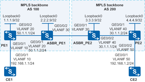
MPLS backbone networks in the same AS use IS-IS as the IGP protocol.
Configuration Roadmap
Because PE1 and PE2 connect to AS 100 and AS 200 and need to provide VPN services, inter-AS solution is used. To facilitate configuration for new access users and save network resources, PWE3-OptionA is used.
The configuration roadmap is as follows:
Run an IGP protocol on the backbone network so that devices in an AS can communicate.
Configure basic MPLS functions on the backbone network and establish dynamic LSPs between PEs and ASBR_PEs in the same AS. Establish a remote LDP session if PEs and ASBR PEs are indirectly connected.
Establish MPLS L2VCs between PEs and ASBR PEs in the same AS.
Procedure
- Configure VLANs that each interface belongs to and assign an IP address to each VLANIF interface according to Figure 1. CE1 is used as an example.
# Configure CE1. The configuration on PE1, PE2, ASBR_PE1, ASBR_PE2, and CE2 is similar to the CE1, and is not mentioned here.
<HUAWEI> system-view
[HUAWEI] sysname CE1
[CE1] vlan batch 10
[CE1] interface vlanif 10
[CE1-Vlanif10] ip address 192.168.1.1 255.255.255.0
[CE1-Vlanif10] quit
[CE1] interface gigabitethernet 0/0/1
[CE1-GigabitEthernet0/0/1] port link-type trunk
[CE1-GigabitEthernet0/0/1] port trunk allow-pass vlan 10
[CE1-GigabitEthernet0/0/1] quit
- Configure an IGP protocol on the MPLS backbone network.
Configure an IGP protocol on the MPLS backbone network to ensure that PEs and ASBR_PEs can communicate.
This example uses IS-IS. PE1 is used as an example.
# Configure PE1. The configuration on PE2, ASBR_PE1, and ASBR_PE2 is similar to the PE1, and is not mentioned here.
[PE1] isis 1
[PE1-isis-1] network-entity 10.0000.0000.0001.00
[PE1-isis-1] quit
[PE1] interface loopback 0
[PE1-LoopBack0] ip address 1.1.1.9 255.255.255.255
[PE1-LoopBack0] isis enable 1
[PE1-LoopBack0] quit
[PE1] interface vlanif 20
[PE1-Vlanif20] isis enable 1
[PE1-Vlanif20] quit
The configuration details of other devices are not mentioned here.
After the configuration is complete, the IS-IS neighbor relationship can be established between the ASBR_PE and the PE in the same AS. Run the display isis peer command. You can see that the neighbor relationship is Up.
ASBR_PE1 is used as an example.
[ASBR_PE1] display isis peer

                          Peer information for ISIS(1)

  System Id     Interface          Circuit Id       State HoldTime Type     PRI
-------------------------------------------------------------------------------
0000.0000.0001  Vlanif20           0000.0000.0002    Up   27s      L1(L1L2) 64
0000.0000.0001  Vlanif20           0000.0000.0002    Up   27s      L2(L1L2) 64

Total Peer(s): 2
Run the display ip routing-table command. You can see that the PEs and ASBR PEs can learn the loopback routes of each other.
ASBR_PE1 is used as an example.
[ASBR_PE1] display ip routing-table
Route Flags: R - relay, D - download to fib, T - to vpn-instance
------------------------------------------------------------------------------
Routing Tables: Public
         Destinations : 6        Routes : 6

Destination/Mask    Proto   Pre  Cost      Flags NextHop         Interface

        1.1.1.9/32  ISIS-L1 15   10          D  50.1.1.1        Vlanif20
        2.2.2.9/32  Direct  0    0           D  127.0.0.1       LoopBack0
       50.1.1.0/24  Direct  0    0           D  50.1.1.2        Vlanif20
       50.1.1.2/32  Direct  0    0           D  127.0.0.1       Vlanif20
       127.0.0.0/8  Direct 0    0           D  127.0.0.1       InLoopBack0
      127.0.0.1/32  Direct 0    0           D  127.0.0.1       InLoopBack0
ASBR_PEs and PEs in the same AS can ping each other successfully.
- Enable MPLS and configure a dynamic LSP.
Configure basic MPLS functions on the MPLS backbone network. Establish a dynamic LDP LSP between the PE and ASBR PE in the same AS.
# Configure PE1. The configuration on PE2, ASBR_PE1, and ASBR_PE2 is similar to the PE1, and is not mentioned here.
[PE1] mpls lsr-id 1.1.1.9
[PE1] mpls
[PE1-mpls] quit
[PE1] mpls ldp
[PE1-mpls-ldp] quit
[PE1] interface vlanif 20
[PE1-Vlanif20] mpls
[PE1-Vlanif20] mpls ldp
[PE1-Vlanif20] quit
After this step is performed, an LSP tunnel is established between the PE and ASBR PE in the same AS.
ASBR_PE1 is used as an example.
[ASBR_PE1] display mpls ldp session

 LDP Session(s) in Public Network
 Codes: LAM(Label Advertisement Mode), SsnAge Unit(DDDD:HH:MM)
 A '*' before a session means the session is being deleted.
 ------------------------------------------------------------------------------
 PeerID             Status      LAM  SsnRole  SsnAge      KASent/Rcv
 ------------------------------------------------------------------------------
 1.1.1.9:0          Operational DU   Active   0000:00:19  79/79
 ------------------------------------------------------------------------------
 TOTAL: 1 session(s) Found.
- Configure MPLS L2VCs.
Configure the L2VC on the U-PE and ASBR PE and connect the U-PE to the CE.
# Configure PE1.In this example, a VLANIF interface is used as the AC-side interface, so you need to run the lnp disable command in the system view before performing the following steps. If you cannot disable LNP on the live network, do not use a VLANIF interface as the AC-side interface.
[PE1] mpls l2vpn
[PE1-l2vpn] quit
[PE1] interface vlanif 10
[PE1-Vlanif10] mpls l2vc 2.2.2.9 100
[PE1-Vlanif10] quit
# Configure ASBR_PE1.In this example, a VLANIF interface is used as the AC-side interface, so you need to run the lnp disable command in the system view before performing the following steps. If you cannot disable LNP on the live network, do not use a VLANIF interface as the AC-side interface.
[ASBR_PE1] mpls l2vpn
[ASBR_PE1-l2vpn] quit
[ASBR_PE1] interface vlanif 30
[ASBR_PE1-Vlanif30] mpls l2vc 1.1.1.9 100
[ASBR_PE1-Vlanif30] quit
# Configure ASBR_PE2.In this example, a VLANIF interface is used as the AC-side interface, so you need to run the lnp disable command in the system view before performing the following steps. If you cannot disable LNP on the live network, do not use a VLANIF interface as the AC-side interface.
[ASBR_PE2] mpls l2vpn
[ASBR_PE2-l2vpn] quit
[ASBR_PE2] interface vlanif 30
[ASBR_PE2-Vlanif30] mpls l2vc 4.4.4.9 100
[ASBR_PE2-Vlanif30] quit
# Configure PE2.In this example, a VLANIF interface is used as the AC-side interface, so you need to run the lnp disable command in the system view before performing the following steps. If you cannot disable LNP on the live network, do not use a VLANIF interface as the AC-side interface.
[PE2] mpls l2vpn
[PE2-l2vpn] quit
[PE2] interface vlanif 50
[PE2-Vlanif50] mpls l2vc 3.3.3.9 100
[PE2-Vlanif50] quit
# Configure CE1.
[CE1] interface vlanif 10
[CE1-Vlanif10] ip address 192.168.1.1 255.255.255.0
[CE1-Vlanif10] quit
# Configure CE2.
[CE2] interface vlanif 50
[CE2-Vlanif50] ip address 192.168.1.2 255.255.255.0
[CE2-Vlanif50] quit
- Verify the configuration.
Display information about the L2VPN connection on PEs. You can see that an L2VC is set up and the VC status is Up.
The display on PE1 is used as an example.
[PE1] display mpls l2vc interface vlanif 10
 *client interface       : Vlanif10 is up
  Administrator PW       : no
  session state          : up
  AC status              : up
  Ignore AC state        : disable
  VC state               : up
  Label state            : 0
  Token state            : 0
  VC ID                  : 100
  VC type                : VLAN
  destination            : 2.2.2.9
  local group ID         : 0            remote group ID      : 0
  local VC label         : 8195        remote VC label      : 8195
  local AC OAM State     : up
  local PSN OAM State    : up
  local forwarding state : forwarding
  local status code      : 0x0
  remote AC OAM state    : up
  remote PSN OAM state   : up
  remote forwarding state: forwarding
  remote status code     : 0x0
  ignore standby state   : no
  BFD for PW             : unavailable
  VCCV State             : up
  manual fault           : not set
  active state           : active
  forwarding entry       : exist
  link state             : up
  local VC MTU           : 1500         remote VC MTU        : 1500
  local VCCV             : alert ttl lsp-ping bfd
  remote VCCV            : alert ttl lsp-ping bfd
  local control word     : disable      remote control word  : disable
  tunnel policy name     : --
  PW template name       : --
  primary or secondary   : primary
  load balance type      : flow
  Access-port            : false
  Switchover Flag        : false
  VC tunnel/token info   : 1 tunnels/tokens
    NO.0  TNL type       : lsp   , TNL ID : 0x20021
    Backup TNL type      : lsp   , TNL ID : 0x0
  create time            : 0 days, 0 hours, 8 minutes, 8 seconds
  up time                : 0 days, 0 hours, 7 minutes, 26 seconds
  last change time       : 0 days, 0 hours, 7 minutes, 26 seconds
  VC last up time        : 2008/07/24 12:31:31
  VC total up time       : 0 days, 2 hours, 12 minutes, 51 seconds
  CKey                   : 11
  NKey                   : 10
  PW redundancy mode     : frr
  AdminPw interface      : --
  AdminPw link state     : --
  Diffserv Mode          : uniform
  Service Class          : be
  Color                  : --
  DomainId               : --
  Domain Name            : --
CE1 and CE2 can ping each other successfully.
The display on CE1 is used as an example.
[CE1] ping 192.168.1.2
  PING 192.168.1.2: 56  data bytes, press CTRL_C to break
    Reply from 192.168.1.2: bytes=56 Sequence=1 ttl=255 time=430 ms
    Reply from 192.168.1.2: bytes=56 Sequence=2 ttl=255 time=220 ms
    Reply from 192.168.1.2: bytes=56 Sequence=3 ttl=255 time=190 ms
    Reply from 192.168.1.2: bytes=56 Sequence=4 ttl=255 time=190 ms
    Reply from 192.168.1.2: bytes=56 Sequence=5 ttl=255 time=190 ms

  --- 192.168.1.2 ping statistics ---
    5 packet(s) transmitted
    5 packet(s) received
    0.00% packet loss
    round-trip min/avg/max = 190/244/430 ms
Configuration Files
CE1 configuration file
#
sysname CE1
#
vlan batch 10
#
interface Vlanif10
 ip address 192.168.1.1 255.255.255.0
#
interface GigabitEthernet0/0/1
 port link-type trunk
 port trunk allow-pass vlan 10
#
return
PE1 configuration file

The lnp disable command has no impact on services before the device restarts. After the device restarts, the device can only forward packets from the VLANs specified by the port default vlan command at Layer 2. The port default vlan 1 command is configured by default, so only packets of VLAN 1 can be forwarded at Layer 2.
#
sysname PE1
#
vlan batch 10 20
#
lnp disable #mpls lsr-id 1.1.1.9
mpls
#
mpls l2vpn
#
mpls ldp
#
isis 1
 network-entity 10.0000.0000.0001.00
#
interface Vlanif10
 mpls l2vc 2.2.2.9 100
#
interface Vlanif20
 ip address 50.1.1.1 255.255.255.0
 isis enable 1
 mpls
 mpls ldp
#
interface GigabitEthernet0/0/1
 port link-type trunk
 port trunk allow-pass vlan 10
#
interface GigabitEthernet0/0/2
 port link-type trunk
 port trunk allow-pass vlan 20
#
interface LoopBack0
 ip address 1.1.1.9 255.255.255.255
 isis enable 1
#
return
ASBR_PE1 configuration file
The lnp disable command has no impact on services before the device restarts. After the device restarts, the device can only forward packets from the VLANs specified by the port default vlan command at Layer 2. The port default vlan 1 command is configured by default, so only packets of VLAN 1 can be forwarded at Layer 2.
#
sysname ASBR_PE1
#
vlan batch 20 30
#
lnp disable #mpls lsr-id 2.2.2.9
mpls
#
mpls l2vpn
#
mpls ldp
#
isis 1
 network-entity 10.0000.0000.0002.00
#
interface Vlanif20
 ip address 50.1.1.2 255.255.255.0
 isis enable 1
 mpls
 mpls ldp
#
interface Vlanif30
 mpls l2vc 1.1.1.9 100
#
interface GigabitEthernet0/0/1
 port link-type trunk
 port trunk allow-pass vlan 20
#
interface GigabitEthernet0/0/2
 port link-type trunk
 port trunk allow-pass vlan 30
#
interface LoopBack0
 ip address 2.2.2.9 255.255.255.255
 isis enable 1
#
return
ASBR_PE2 configuration file
The lnp disable command has no impact on services before the device restarts. After the device restarts, the device can only forward packets from the VLANs specified by the port default vlan command at Layer 2. The port default vlan 1 command is configured by default, so only packets of VLAN 1 can be forwarded at Layer 2.
#
sysname ASBR_PE2
#
vlan batch 30 40
#
lnp disable #mpls lsr-id 3.3.3.9
mpls
#
mpls l2vpn
#
mpls ldp
#
isis 1
 network-entity 10.0000.0000.0003.00
#
interface Vlanif30
 mpls l2vc 4.4.4.9 100
#
interface Vlanif40
 ip address 30.1.1.1 255.255.255.0
 isis enable 1
 mpls
 mpls ldp
#
interface GigabitEthernet0/0/1
 port link-type trunk
 port trunk allow-pass vlan 30
#
interface GigabitEthernet0/0/2
 port link-type trunk
 port trunk allow-pass vlan 40
#
interface LoopBack0
 ip address 3.3.3.9 255.255.255.255
 isis enable 1
#
return
PE2 configuration file
The lnp disable command has no impact on services before the device restarts. After the device restarts, the device can only forward packets from the VLANs specified by the port default vlan command at Layer 2. The port default vlan 1 command is configured by default, so only packets of VLAN 1 can be forwarded at Layer 2.
#
sysname PE2
#
vlan batch 40 50
#
lnp disable #mpls lsr-id 4.4.4.9
mpls
#
mpls l2vpn
#
mpls ldp
#
isis 1
 network-entity 10.0000.0000.0004.00
#
interface Vlanif40
 ip address 30.1.1.2 255.255.255.0
 isis enable 1
 mpls
 mpls ldp
#
interface Vlanif50
 mpls l2vc 3.3.3.9 100
#
interface GigabitEthernet0/0/1
 port link-type trunk
 port trunk allow-pass vlan 40
#
interface GigabitEthernet0/0/2
 port link-type trunk
 port trunk allow-pass vlan 50
#
interface LoopBack0
 ip address 4.4.4.9 255.255.255.255
 isis enable 1
#
return
CE2 configuration file
#
sysname CE2
#
vlan batch 50
#
interface Vlanif50
 ip address 192.168.1.2 255.255.255.0
#
interface GigabitEthernet0/0/1
 port link-type trunk
 port trunk allow-pass vlan 50
#
return