Example for Configuring Traffic Shaping (Based on 802.1p Priority Trust)
Overview
Traffic shaping adjusts the rate of outgoing traffic to ensure even transmission. Traffic shaping uses the buffer and token bucket to control traffic. When packets are sent at a high rate, traffic shaping caches packets in the buffer and then evenly sends these cached packets based on the token bucket.
Traffic shaping is often configured on the downstream device to prevent packet loss caused by congestion. For example, the headquarters connects to its branch through a leased line that has finite bandwidth. Traffic policing is configured on the headquarters edge device to limit the packet sending rate. In this situation, traffic shaping can be configured on the branch edge device to cache excess packets, preventing packet loss.
Configuration Notes
For applicable product models and versions, see Applicable Product Models and Versions.

For details about software mappings, visit Hardware Query Tool and search for the desired product model.
Networking Requirements
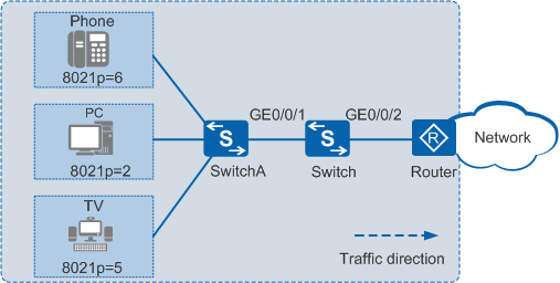
In Figure 1, the Switch is connected to the router through GE0/0/2. The 802.1p priorities of voice, video, and data services are 6, 5, and 2, respectively, and these services can reach residential users through the router and Switch. The transmission rate of traffic from the user LAN is higher than the transmission rate of traffic from the router; therefore, jitter may occur on GE0/0/2. To prevent jitter and ensure bandwidth of services, ensure that:
The CIR of the interface is 10000 kbit/s.
The CIR and PIR for the voice service are 3000 kbit/s and 5000 kbit/s respectively.
The CIR and PIR for the video service are 5000 kbit/s and 8000 kbit/s respectively.
The CIR and PIR for the data service are 2000 kbit/s and 3000 kbit/s respectively.
Configuration Roadmap
- Create a VLAN and configure interfaces so that users can access the Internet through the Switch.
Configure an interface to trust 802.1p priorities of packets.
Configure traffic shaping on an interface to limit the bandwidth of the interface.
Configure traffic shaping on queues of the interface to limit the bandwidth of voice, video, and data services.
Procedure
- Create a VLAN and configure interfaces.
# Create VLAN 10.
<HUAWEI> system-view
[HUAWEI] sysname Switch
[Switch] vlan batch 10
# Configure GE0/0/1 and GE0/0/2 as trunk interfaces and add them to VLAN 10.
[Switch] interface gigabitethernet 0/0/1
[Switch-GigabitEthernet0/0/1] port link-type trunk
[Switch-GigabitEthernet0/0/1] port trunk allow-pass vlan 10
[Switch-GigabitEthernet0/0/1] quit
[Switch] interface gigabitethernet 0/0/2
[Switch-GigabitEthernet0/0/2] port link-type trunk
[Switch-GigabitEthernet0/0/2] port trunk allow-pass vlan 10
[Switch-GigabitEthernet0/0/2] quit
# Create VLANIF 10 and set its IP address to 10.10.10.2/24.
[Switch] interface vlanif 10
[Switch-Vlanif10] ip address 10.10.10.2 255.255.255.0
[Switch-Vlanif10] quit
On the router, set the IP address of the interface connected to the Switch to 10.10.10.1/24, and configure a sub-interface on the interface to terminate the VLAN.
- Configure an interface to trust packet priorities.
# Configure an interface to trust 802.1p priorities of packets.
[Switch] interface gigabitethernet 0/0/1
[Switch-GigabitEthernet0/0/1] trust 8021p  //Configure the interface to trust 802.1p priorities. That is, packets enter different queues according to the default mapping between 802.1p priorities and local priorities.
[Switch-GigabitEthernet0/0/1] quit
- Configure traffic shaping on an interface.
# Configure traffic shaping on an interface of the Switch to limit the CIR of the interface to 10000 kbit/s.
[Switch] interface gigabitethernet 0/0/2
[Switch-GigabitEthernet0/0/2] qos lr outbound cir 10000  //Configure interface-based rate limiting in the outbound direction to limit the total bandwidth.
- Configure traffic shaping on queues of the interface.
# Configure traffic shaping on queues of the interface on the Switch to set the CIR values of voice, video, and data services to 3000 kbit/s, 5000 kbit/s, and 2000 kbit/s respectively and their PIR values to 5000 kbit/s, 8000 kbit/s, and 3000 kbit/s respectively.
[Switch-GigabitEthernet0/0/2] qos queue 6 shaping cir 3000 pir 5000  //Set the CIR of voice packets in queue 6 to 3000 kbit/s.
[Switch-GigabitEthernet0/0/2] qos queue 5 shaping cir 5000 pir 8000
[Switch-GigabitEthernet0/0/2] qos queue 2 shaping cir 2000 pir 3000
[Switch-GigabitEthernet0/0/2] quit
- Verify the configuration.
# After the configuration is complete, the CIR of packets sent from GE0/0/2 is 10000 kbit/s; the CIR of the voice service packets is 3000 kbit/s and PIR is 5000 kbit/s; the CIR of the video service packets is 5000 kbit/s and the PIR is 8000 kbit/s; the CIR of the data service packets is 2000 kbit/s and the PIR is 3000 kbit/s.
Configuration Files
Switch configuration file
#
sysname Switch
#
vlan batch 10
#
interface Vlanif10
 ip address 10.10.10.2 255.255.255.0
#
interface GigabitEthernet0/0/1
 port link-type trunk
 port trunk allow-pass vlan 10
 trust 8021p
#
interface GigabitEthernet0/0/2
 port link-type trunk
 port trunk allow-pass vlan 10
 qos lr outbound cir 10000 cbs 1250000
 qos queue 2 shaping cir 2000 pir 3000
 qos queue 5 shaping cir 5000 pir 8000
 qos queue 6 shaping cir 3000 pir 5000
#
return
Applicable Product Models and Versions
Product |
Product Model |
Software Version |
|---|---|---|
S2700 |
S2752EI |
V100R006C05 |
S2720-EI |
V200R006C10, V200R009C00, V200R010C00, V200R011C10, V200R012C00, V200R013C00, V200R019C00, V200R019C10 |
|
S2750-EI |
V200R003C00, V200R005C00SPC300, V200R006C00, V200R007C00, V200R008C00, V200R009C00, V200R010C00, V200R011C00, V200R011C10, V200R012C00 |
|
S3700 |
S3700-SI and S3700-EI |
V100R006C05 |
S3700-HI |
V200R001C00 |
|
S5700 |
S5700-LI |
V200R001C00, V200R002C00, V200R003(C00&C02&C10), V200R005C00SPC300, V200R006C00, V200R007C00, V200R008C00, V200R009C00, V200R010C00, V200R011C00, V200R011C10, V200R012C00 |
S5700S-LI |
V200R001C00, V200R002C00, V200R003C00, V200R005C00SPC300, V200R006C00, V200R007C00, V200R008C00, V200R009C00, V200R010C00, V200R011C00, V200R011C10, V200R012C00 |
|
S5700-SI |
V200R001C00, V200R002C00, V200R003C00, V200R005C00 |
|
S5700-EI |
V200R001(C00&C01), V200R002C00, V200R003C00, V200R005(C00&C01&C02&C03) |
|
S5710-C-LI |
V200R001C00 |
|
S5710-X-LI |
V200R008C00, V200R009C00, V200R010C00, V200R011C00, V200R011C10, V200R012C00 |
|
S5720-LI and S5720S-LI |
V200R010C00, V200R011C00, V200R011C10, V200R012(C00&C20), V200R013C00, V200R019C00, V200R019C10 |
|
S5720-SI and S5720S-SI |
V200R008C00, V200R009C00, V200R010C00, V200R011C00, V200R011C10, V200R012C00, V200R013C00, V200R019C00, V200R019C10 |
|
S5720I-SI |
V200R012C00, V200R013C00, V200R019C00, V200R019C10 |
|
S5730-SI |
V200R011C10, V200R012C00, V200R013C00, V200R019C00, V200R019C10 |
|
S5730S-EI |
V200R011C10, V200R012C00, V200R013C00, V200R019C00, V200R019C10 |
|
S5735-L, S5735S-L |
V200R019C00, V200R019C10 |
|
S5735S-L-M |
V200R019C00, V200R019C10 |
|
S5735-S, S5735S-S |
V200R019C00, V200R019C10 |
|
S5700 |
S5735-S-I |
V200R019C10 |
S6700 |
S6720-LI and S6720S-LI |
V200R011C00, V200R011C10, V200R012C00, V200R013C00, V200R019C00, V200R019C10 |
S6720-SI and S6720S-SI |
V200R011C00, V200R011C10, V200R012C00, V200R013C00, V200R019C00, V200R019C10 |