Example for Configuring Congestion Management (Schedule Template Mode)
Overview
Congestion management implements queuing and scheduling when sending packet flows. The device provides the following congestion management technologies: Priority Queuing (PQ), Weighted Deficit Round Robin (WDRR), Weighted Round Robin (WRR), PQ+WDRR, and PQ+WRR. The device has eight queues on each interface in the outbound direction, which are identified by index numbers 0 to 7. Based on the mappings between local priorities and queues, the device sends the classified packets to queues, and then schedules the packets using queue scheduling mechanisms.
This example uses PQ+WRR to implement congestion management. In WRR scheduling, the device performs scheduling in a polling manner according to the weight of each queue. The number of times packets are scheduled in each queue is in directly proportional to the weight of the queue. A higher weight indicates more packet scheduling times.
Configuration Notes
For applicable product models and versions, see Applicable Product Models and Versions.

For details about software mappings, visit Hardware Query Tool and search for the desired product model.
Networking Requirements
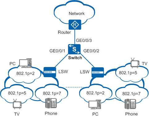
In Figure 1, the Switch is connected to the router through GE0/0/3. The 802.1p priorities of voice, video, and data services are 7, 5, and 2, respectively, and these services can reach residential users through the router and Switch. To reduce the impact of network congestion and ensure bandwidth for high-priority and delay-sensitive services, set parameters according to the following table.
Service Type |
CoS Value |
WRR Weight |
|---|---|---|
Voice |
CS7 |
0 |
Video |
EF |
20 |
Data |
AF2 |
10 |
Configuration Roadmap
Configure a VLAN for each interface so that devices can communicate with each other at the link layer.
Configure an interface to trust 802.1p priorities of packets.
Configure a scheduling profile and apply the scheduling profile to the interface.
Procedure
- Configure a VLAN for each interface so that devices can communicate with each other at the link layer.
<HUAWEI> system-view
[HUAWEI] sysname Switch
[Switch] vlan batch 10 20 30
[Switch] interface gigabitethernet 0/0/1
[Switch-GigabitEthernet0/0/1] port link-type trunk
[Switch-GigabitEthernet0/0/1] port trunk allow-pass vlan 10 20 30
[Switch-GigabitEthernet0/0/1] quit
[Switch] interface gigabitethernet 0/0/2
[Switch-GigabitEthernet0/0/2] port link-type trunk
[Switch-GigabitEthernet0/0/2] port trunk allow-pass vlan 10 20 30
[Switch-GigabitEthernet0/0/2] quit
[Switch] interface gigabitethernet 0/0/3
[Switch-GigabitEthernet0/0/3] port link-type trunk
[Switch-GigabitEthernet0/0/3] port trunk allow-pass vlan 10 20 30
[Switch-GigabitEthernet0/0/3] quit
- Configure an interface to trust 802.1p priorities of packets.
[Switch] interface gigabitethernet 0/0/3
[Switch-GigabitEthernet0/0/3] trust 8021p  //Configure the interface to trust 802.1p priorities. That is, packets enter different queues according to the default mapping between 802.1p priorities and local priorities.
[Switch-GigabitEthernet0/0/3] quit
- Configure congestion management.
# Create a scheduling profile and set queue scheduling parameters. By default, WRR is used.
[Switch] qos schedule-profile p1
[Switch-qos-schedule-profile-p1] qos queue 7 wrr weight 0  //Set the weight of queue 7 to 0 and configure PQ for queue 7.
[Switch-qos-schedule-profile-p1] qos queue 5 wrr weight 20  //Set the WRR weight of queue 5 to 20.
[Switch-qos-schedule-profile-p1] qos queue 2 wrr weight 10  //Set the WRR weight of queue 2 to 10. The weight ratio of queue 5 and queue 2 is 2:1.
[Switch-qos-schedule-profile-p1] quit
# Apply the scheduling profile to GE 0/0/1 and GE 0/0/2 of the Switch.
[Switch] interface gigabitethernet 0/0/1
[Switch-GigabitEthernet0/0/1] qos schedule-profile p1  //Apply the scheduling profile to GE0/0/1.
[Switch-GigabitEthernet0/0/1] quit
[Switch] interface gigabitethernet 0/0/2
[Switch-GigabitEthernet0/0/2] qos schedule-profile p1  //Apply the scheduling profile to GE0/0/2.
[Switch-GigabitEthernet0/0/2] quit
- Verify the configuration.
# Check the scheduling profile and queue scheduling parameters.
[Switch] qos schedule-profile p1
[Switch-qos-schedule-profile-p1] display this
#
 qos schedule-profile p1
   qos queue 2 wrr weight 10
   qos queue 5 wrr weight 20
   qos queue 7 wrr weight 0
#
return
Configuration Files
Switch configuration file
#
sysname Switch
#
vlan batch 10 20 30
#
interface GigabitEthernet0/0/1
 port link-type trunk
 port trunk allow-pass vlan 10 20 30
 qos schedule-profile p1
 #
interface GigabitEthernet0/0/2
 port link-type trunk
 port trunk allow-pass vlan 10 20 30
 qos schedule-profile p1
#
interface GigabitEthernet0/0/3
 port link-type trunk
 port trunk allow-pass vlan 10 20 30
 trust 8021p
#
 qos schedule-profile p1
   qos queue 2 wrr weight 10
   qos queue 5 wrr weight 20
   qos queue 7 wrr weight 0
#
return
Applicable Product Models and Versions
Product |
Product Model |
Software Version |
|---|---|---|
S2700 |
S2720-EI |
V200R006C10, V200R009C00, V200R010C00, V200R011C10, V200R012C00, V200R013C00, V200R019C00, V200R019C10 |
S2750-EI |
V200R003C00, V200R005C00SPC300, V200R006C00, V200R007C00, V200R008C00, V200R009C00, V200R010C00, V200R011C00, V200R011C10, V200R012C00 |
|
S5700 |
S5700-LI |
V200R001C00, V200R002C00, V200R003(C00&C02&C10), V200R005C00SPC300, V200R006C00, V200R007C00, V200R008C00, V200R009C00, V200R010C00, V200R011C00, V200R011C10, V200R012C00 |
S5700S-LI |
V200R001C00, V200R002C00, V200R003C00, V200R005C00SPC300, V200R006C00, V200R007C00, V200R008C00, V200R009C00, V200R010C00, V200R011C00, V200R011C10, V200R012C00 |
|
S5700-SI |
V200R001C00, V200R002C00, V200R003C00, V200R005C00 |
|
S5710-C-LI |
V200R001C00 |
|
S5710-X-LI |
V200R008C00, V200R009C00, V200R010C00, V200R011C00, V200R011C10, V200R012C00 |
|
S5720-LI, S5720S-LI |
V200R010C00, V200R011C00, V200R011C10, V200R012(C00&C20), V200R013C00, V200R019C00, V200R019C10 |
|
S5720-SI, S5720S-SI |
V200R008C00, V200R009C00, V200R010C00, V200R011C00, V200R011C10, V200R012C00, V200R013C00, V200R019C00, V200R019C10 |
|
S5720I-SI |
V200R012C00, V200R013C00, V200R019C00, V200R019C10 |
|
S5730-SI |
V200R011C10, V200R012C00, V200R013C00, V200R019C00, V200R019C10 |
|
S5730S-EI |
V200R011C10, V200R012C00, V200R013C00, V200R019C00, V200R019C10 |
|
S6700 |
S6720-LI, S6720S-LI |
V200R011C00, V200R011C10, V200R012C00, V200R013C00, V200R019C00, V200R019C10 |
S6720-SI, S6720S-SI |
V200R011C00, V200R011C10, V200R012C00, V200R013C00, V200R019C00, V200R019C10 |