Example for Configuring Congestion Avoidance and Congestion Management (Using PQ+WDRR Scheduling and a WRED Profile)
Overview
Congestion management implements queuing and scheduling when sending packet flows. Based on the queuing and scheduling policies, the device provides the following congestion management technologies: Priority Queuing (PQ), Weighted Deficit Round Robin (WDRR), Weighted Round Robin (WRR), PQ+WDRR, and PQ+WRR. The device has eight queues on each interface in the outbound direction, which are identified by index numbers 0 to 7. Based on the mappings between local priorities and queues, the device sends the classified packets to queues, and then schedules the packets using queue scheduling mechanisms.
Congestion avoidance is a flow control mechanism. A system configured with congestion avoidance monitors network resource usage such as queues and memory buffers. When congestion occurs or aggravates, the system discards packets. Congestion avoidance uses tail drop and random drop policies to discard packets. Random drop policies include the Simple Random Early Detection (SRED) and Weighted Random Early Detection (WRED).
This example uses PQ+WDRR scheduling to implement congestion management. In WRR scheduling, the number of times packets are scheduled in each queue is directly proportional to the weight of this queue. A higher weight indicates more times packets are scheduled. WRR schedules packets based on the number of packets. That is, large-sized packets are more likely to be scheduled and obtain more bandwidth. WDRR schedules packets considering the packet length, ensuring that packets are scheduled with the same probability. WRED is configured to implement congestion avoidance. The device discards excess traffic according to the maximum drop probability.
Configuration Notes
For applicable product models and versions, see Applicable Product Models and Versions. This example does not apply to X series cards because they do not support the qos wred command.

For details about software mappings, visit Hardware Query Tool and search for the desired product model.
Networking Requirements
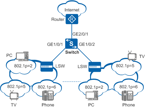
In Figure 1, the Switch is connected to the router through GE2/0/1. The 802.1p priorities of voice, video, and data services from the Internet are 6, 5, and 2, respectively, and these services can reach residential users through the router and Switch. On the Switch, the rate of GE2/0/1 (inbound interface) is higher than the rates of GE1/0/1 and GE1/0/2 (outbound interfaces), so congestion may occur on the two outbound interfaces.
To reduce the impact of network congestion and ensure bandwidth for high-priority and delay-sensitive services, set parameters according to Table 1 and Table 2.
Service Type |
Color |
Lower Drop Threshold (%) |
Upper Drop Threshold (%) |
Maximum Drop Probability |
|---|---|---|---|---|
Voice |
Green |
80 |
100 |
10 |
Video |
Yellow |
60 |
80 |
20 |
Data |
Red |
40 |
60 |
40 |
Configuration Roadmap
Configure a VLAN for each interface so that devices can communicate with each other at the link layer.
Create a DiffServ domain on the Switch to map 802.1p priorities of different service packets to PHBs and colors, and bind the DiffServ domain to the inbound interface of the Switch.
Configure a WRED profile on the Switch and apply the WRED profile to the outbound interfaces.
Set scheduling parameters of each queue on the outbound interface of the Switch.
Procedure
- Configure a VLAN for each interface so that devices can communicate with each other at the link layer.
<HUAWEI> system-view
[HUAWEI] sysname Switch
[Switch] vlan batch 2 5 6
[Switch] interface gigabitethernet 1/0/1
[Switch-GigabitEthernet1/0/1] port link-type trunk
[Switch-GigabitEthernet1/0/1] port trunk allow-pass vlan 2 5 6
[Switch-GigabitEthernet1/0/1] quit
[Switch] interface gigabitethernet 1/0/2
[Switch-GigabitEthernet1/0/2] port link-type trunk
[Switch-GigabitEthernet1/0/2] port trunk allow-pass vlan 2 5 6
[Switch-GigabitEthernet1/0/2] quit
[Switch] interface gigabitethernet 2/0/1
[Switch-GigabitEthernet2/0/1] port link-type trunk
[Switch-GigabitEthernet2/0/1] port trunk allow-pass vlan 2 5 6
[Switch-GigabitEthernet2/0/1] quit
- Configure priority mapping.
# Create a DiffServ domain ds1 to map 802.1p priorities 6, 5, 2 to PHBs of EF, AF3, and AF1 and colors of green, yellow, and red respectively.
[Switch] diffserv domain ds1
[Switch-dsdomain-ds1] 8021p-inbound 6 phb ef green  //Create a DiffServ domain to map 802.1p priorities of different service packets to PHBs so that packets enter different queues.
[Switch-dsdomain-ds1] 8021p-inbound 5 phb af3 yellow
[Switch-dsdomain-ds1] 8021p-inbound 2 phb af1 red
[Switch-dsdomain-ds1] quit
# Bind the DiffServ domain to GE2/0/1 of the Switch.
[Switch] interface gigabitethernet 2/0/1
[Switch-GigabitEthernet2/0/1] trust upstream ds1  //Apply the DiffServ domain to the interface.
[Switch-GigabitEthernet2/0/1] trust 8021p inner  //Configure the interface to trust 802.1p priorities.
[Switch-GigabitEthernet2/0/1] quit
- Configure congestion avoidance.
# Create a WRED profile wred1 on the Switch and set scheduling parameters in the WRED profile.
[Switch] drop-profile wred1
[Switch-drop-wred1] color green low-limit 80 high-limit 100 discard-percentage 10  //Configure a WRED drop profile, and set the upper and lower drop threshold and maximum drop probability for green packets.
[Switch-drop-wred1] color yellow low-limit 60 high-limit 80 discard-percentage 20  //When the percentage of the yellow packet length to the queue length reaches 60%, the device starts to discard packets with the maximum drop probability of 20%. When the percentage of the yellow packet length to the queue length reaches 80%, the device discards all new packets.
[Switch-drop-wred1] color red low-limit 40 high-limit 60 discard-percentage 40
[Switch-drop-wred1] quit
# Apply the WRED profile wred1 to GE1/0/1 and GE1/0/2 on the Switch.
[Switch] interface gigabitethernet 1/0/1
[Switch-GigabitEthernet1/0/1] qos wred wred1
[Switch-GigabitEthernet1/0/1] qos queue 5 wred wred1
[Switch-GigabitEthernet1/0/1] qos queue 3 wred wred1
[Switch-GigabitEthernet1/0/1] qos queue 1 wred wred1
[Switch-GigabitEthernet1/0/1] quit
[Switch] interface gigabitethernet 1/0/2
[Switch-GigabitEthernet1/0/2] qos wred wred1
[Switch-GigabitEthernet1/0/2] qos queue 5 wred wred1
[Switch-GigabitEthernet1/0/2] qos queue 3 wred wred1
[Switch-GigabitEthernet1/0/2] qos queue 1 wred wred1
[Switch-GigabitEthernet1/0/2] quit
- Configure congestion management.
# Set scheduling parameters of each queue on GE1/0/1 and GE1/0/2 of the Switch.
The following steps are applicable to only the chassis switch.
[Switch] interface gigabitethernet 1/0/1
[Switch-GigabitEthernet1/0/1] qos pq 5  //Configure PQ scheduling for queue 5.
[Switch-GigabitEthernet1/0/1] qos drr 0 to 4  //Configure WDRR scheduling for queues 0 to 4.
[Switch-GigabitEthernet1/0/1] qos queue 3 drr weight 100  //Set the WDRR weight of queue 3 to 100.
[Switch-GigabitEthernet1/0/1] qos queue 1 drr weight 50  //Set the WDRR weight of queue 1 to 50. The device schedules packets in queue 1 and queue 3 according to the ratio of 1:2.
[Switch-GigabitEthernet1/0/1] quit
[Switch] interface gigabitethernet 1/0/2
[Switch-GigabitEthernet1/0/2] qos pq 5
[Switch-GigabitEthernet1/0/2] qos drr 0 to 4
[Switch-GigabitEthernet1/0/2] qos queue 3 drr weight 100
[Switch-GigabitEthernet1/0/2] qos queue 1 drr weight 50
[Switch-GigabitEthernet1/0/2] quit
The following steps are applicable to only the box switch.
[Switch] interface gigabitethernet 1/0/1
[Switch-GigabitEthernet1/0/1] qos drr  //Configure WDRR on the interface. By default, WRR is used on an interface.
[Switch-GigabitEthernet1/0/1] qos queue 5 drr weight 0  //Set the WDRR weight of queue 5 to 0 and use PQ scheduling.
[Switch-GigabitEthernet1/0/1] qos queue 3 drr weight 100  //Set the WDRR weight of queue 3 to 100.
[Switch-GigabitEthernet1/0/1] qos queue 1 drr weight 50  //Set the WDRR weight of queue 1 to 50. The device schedules packets in queue 3 and queue 1 according to the ratio of 2:1.
[Switch-GigabitEthernet1/0/1] quit
[Switch] interface gigabitethernet 1/0/2
[Switch-GigabitEthernet1/0/2] qos drr
[Switch-GigabitEthernet1/0/2] qos queue 5 drr weight 0
[Switch-GigabitEthernet1/0/2] qos queue 3 drr weight 100
[Switch-GigabitEthernet1/0/2] qos queue 1 drr weight 50
[Switch-GigabitEthernet1/0/2] quit
- Verify the configuration.
# Check the configuration of the DiffServ domain ds1.
[Switch] display diffserv domain name ds1
diffserv domain name:ds1
 8021p-inbound 0 phb be green
 8021p-inbound 1 phb af1 green
 8021p-inbound 2 phb af1 red
 8021p-inbound 3 phb af3 green
 8021p-inbound 4 phb af4 green
 8021p-inbound 5 phb af3 yellow
 8021p-inbound 6 phb ef green
 8021p-inbound 7 phb cs7 green
 8021p-outbound be green map 0
......
# Check the WRED profile configuration.
[Switch] display drop-profile name wred1
Drop-profile[1]: wred1
Queue depth    : default
Color     Low-limit   High-limit  Discard-percentage
- - - - - - - - - - - - - - - - - - - - - - - - - - - - - - - - -
Green     80          100         10
Yellow    60          80          20
Red       40          60          40
Non-tcp   100         100         100
-----------------------------------------------------------------
Configuration Files
Switch configuration file (modular switch)
#
sysname Switch
#
vlan batch 2 5 to 6
#
diffserv domain ds1
 8021p-inbound 2 phb af1 red
 8021p-inbound 5 phb af3 yellow
 8021p-inbound 6 phb ef green
#
drop-profile wred1
 color green low-limit 80 high-limit 100 discard-percentage 10
 color yellow low-limit 60 high-limit 80 discard-percentage 20
 color red low-limit 40 high-limit 60 discard-percentage 40
#
interface GigabitEthernet1/0/1
 port link-type trunk
 port trunk allow-pass vlan 2 5 to 6
 qos wred wred1
 qos pq 5 to 7 drr 0 to 4
 qos queue 1 drr weight 50
 qos queue 3 drr weight 100
 qos queue 1 wred wred1
 qos queue 3 wred wred1
 qos queue 5 wred wred1
#
interface GigabitEthernet1/0/2
 port link-type trunk
 port trunk allow-pass vlan 2 5 to 6
 qos wred wred1
 qos pq 5 to 7 drr 0 to 4
 qos queue 1 drr weight 50
 qos queue 3 drr weight 100
 qos queue 1 wred wred1
 qos queue 3 wred wred1
 qos queue 5 wred wred1
#
interface GigabitEthernet2/0/1
 port link-type trunk
 port trunk allow-pass vlan 2 5 to 6
 trust upstream ds1
 trust 8021p inner
#
return
Switch configuration file (fixed switch)
#
sysname Switch
#
vlan batch 2 5 to 6
#
diffserv domain ds1
 8021p-inbound 2 phb af1 red
 8021p-inbound 5 phb af3 yellow
 8021p-inbound 6 phb ef green
#
drop-profile wred1
 color green low-limit 80 high-limit 100 discard-percentage 10
 color yellow low-limit 60 high-limit 80 discard-percentage 20
 color red low-limit 40 high-limit 60 discard-percentage 40
#
interface GigabitEthernet1/0/1
 port link-type trunk
 port trunk allow-pass vlan 2 5 to 6
 qos drr
 qos queue 1 drr weight 50
 qos queue 3 drr weight 100
 qos queue 5 drr weight 0
 qos wred wred1
 qos queue 1 wred wred1
 qos queue 3 wred wred1
 qos queue 5 wred wred1
#
interface GigabitEthernet1/0/2
 port link-type trunk
 port trunk allow-pass vlan 2 5 to 6
 qos drr
 qos queue 1 drr weight 50
 qos queue 3 drr weight 100
 qos queue 5 drr weight 0
 qos wred wred1
 qos queue 1 wred wred1
 qos queue 3 wred wred1
 qos queue 5 wred wred1
#
interface GigabitEthernet2/0/1
 port link-type trunk
 port trunk allow-pass vlan 2 5 to 6
 trust upstream ds1
 trust 8021p inner
#
return
Applicable Product Models and Versions
Product |
Product Model |
Software Version |
|---|---|---|
S3700 |
S3700-HI |
V200R001C00 |
S5700 |
S5700-HI |
V200R001(C00&C01), V200R002C00, V200R003C00, V200R005(C00SPC500&C01&C02) |
S5710-EI |
V200R001C00, V200R002C00, V200R003C00, V200R005(C00&C02) |
|
S5720-EI |
V200R007C00, V200R008C00, V200R009C00, V200R010C00, V200R011C00, V200R011C10, V200R012C00, V200R013C00, V200R019C00, V200R019C10 |
|
S5710-HI |
V200R003C00, V200R005(C00&C02&C03) |
|
S6700 |
S6700-EI |
V200R001(C00&C01), V200R002C00, V200R003C00, V200R005(C00&C01&C02) |
S6720-EI |
V200R008C00, V200R009C00, V200R010C00, V200R011C00, V200R011C10, V200R012C00, V200R013C00, V200R019C00, V200R019C10 |
|
S6720S-EI |
V200R009C00, V200R010C00, V200R011C00, V200R011C10, V200R012C00, V200R013C00, V200R019C00, V200R019C10 |
|
S7700 |
S7703, S7706, S7712 |
V200R001(C00&C01), V200R002C00, V200R003C00, V200R005C00, V200R006C00, V200R007C00, V200R008C00, V200R009C00, V200R010C00, V200R011C10, V200R012C00, V200R013C00, V200R013C02, V200R019C00, V200R019C10 |
S7703 PoE |
V200R013C00, V200R019C00, V200R019C10 |
|
S7706 PoE |
V200R013C00, V200R019C00, V200R019C10 |
|
S9700 |
S9703, S9706, S9712 |
V200R001(C00&C01), V200R002C00, V200R003C00, V200R005C00, V200R006C00, V200R007(C00&C10), V200R008C00, V200R009C00, V200R010C00, V200R011C10, V200R012C00, V200R013C00 |