Example for Configuring a Traffic Policy to Prevent Some Users from Accessing the Internet at the Specified Time
Overview
Modular QoS Command-Line Interface (MQC) allows the device to classify traffic by type, providing the same service for packets of the same type and differentiated services for packets of different types. Filtering specified type of packets can be only implemented through MQC.
When packets of a type are considered untrusted, MQC can be used to differentiate the packets from other types of packets and discard them. When packets of a type are considered trusted, MQC can be used to differentiate the packets from other types of packets and permit them to pass through.
Compared with the blacklist, MQC-based packet filtering classifies packets in a more fine-grained manner and is more flexible to deploy.
Configuration Notes
- S5720-HI in V200R006C00 and later versions
- S5720-EI and S6720-EI in V200R008C00 and later versions
- S6720S-EI in V200R009C00 and later versions
- S5730-HI and S6720-HI in V200R012C00 and later versions
- S5731-H and S6730-H in V200R013C02 and later versions
- S5731-S, S5731S-S, S6730-S, S6730S-S, S5731S-H, and S5732-H in V200R019C00 and later versions
- S6730S-H in V200R019C10 and later versions
For applicable product models and versions, see Applicable Product Models and Versions.

For details about software mappings, visit Hardware Query Tool and search for the desired product model.
Networking Requirements
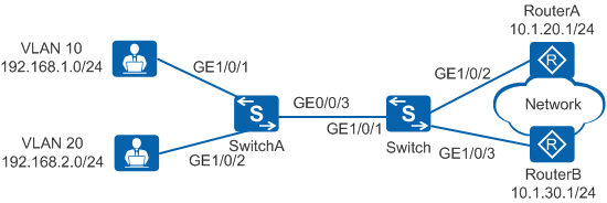
In Figure 1, the company has two departments that belong to VLAN 10 and VLAN 20, respectively. Servers are deployed in VLAN 10 to provide services for internal and external users, and office services of employees are transmitted in VLAN 20. The company requires that employees in VLAN 20 access only servers in VLAN 10 during the working time (8:00 to 18:00).
Device |
Interface |
VLAN |
Layer 3 Interface |
IP Address |
|---|---|---|---|---|
SwitchA |
GigabitEthernet1/0/1 |
VLAN 10 |
- |
192.168.1.1/24 |
GigabitEthernet1/0/2 |
VLAN 20 |
- |
192.168.2.1/24 |
|
GigabitEthernet1/0/3 |
VLAN 10 and VLAN 20 |
- |
192.168.3.1/24 |
|
Switch |
GigabitEthernet1/0/1 |
VLAN 10 and VLAN 20 |
VLANIF 10 and VLANIF 20 |
VLANIF 10: 192.168.1.1/24 VLANIF 20: 192.168.2.1/24 |
GigabitEthernet1/0/2 |
VLAN 30 |
VLANIF 30 |
10.1.20.2/24 |
|
GigabitEthernet1/0/3 |
VLAN 40 |
VLANIF 40 |
10.1.30.2/24 |
Configuration Roadmap
- Create VLANs, and configure interfaces and a routing protocol to implement interworking between the company and external network.
- On the Switch, configure a time range 8:00-18:00 from Monday to Friday so that the device can control traffic based on the time range.
- On the Switch, configure an ACL to match the traffic when employees in VLAN 20 access servers in VLAN 10 based on the time range.
- Configure a traffic classifier on the Switch to classify packets based on the ACL.
- Configure a traffic behavior on the Switch to permit matched traffic to pass through.
- Configure a traffic policy on the Switch, bind the traffic policy to the traffic classifier and traffic behavior, and apply the traffic policy to the inbound direction of GE1/0/1 connected to SwitchA so that employees in VLAN 20 cannot access the Internet during the working time and can access the Internet during the non-working time.
Procedure
- Create VLANs and configure interfaces.
# Configure the switch.
<HUAWEI> system-view
[HUAWEI] sysname Switch
[Switch] vlan batch 10 20 30 40  //Create VLAN 10 to VLAN 40.
[Switch] interface gigabitethernet 1/0/1
[Switch-GigabitEthernet1/0/1] port link-type trunk  //Set the link type of the interface to trunk.
[Switch-GigabitEthernet1/0/1] port trunk allow-pass vlan 10 20  //Add the interface to VLAN 10 and VLAN 20.
[Switch-GigabitEthernet1/0/1] quit
[Switch] interface gigabitethernet 1/0/2
[Switch-GigabitEthernet1/0/2] port link-type access  //Set the link type of the interface to access.
[Switch-GigabitEthernet1/0/2] port default vlan 30  //Add the interface to VLAN 30.
[Switch-GigabitEthernet1/0/2] quit
[Switch] interface gigabitethernet 1/0/3
[Switch-GigabitEthernet1/0/3] port link-type access
[Switch-GigabitEthernet1/0/3] port default vlan 40
[Switch-GigabitEthernet1/0/3] quit
[Switch] interface vlanif 10  //Create a VLANIF interface.
[Switch-Vlanif10] ip address 192.168.1.1 255.255.255.0  //Configure an IP address for the VLANIF interface. The IP address is the gateway address of network segment 192.168.1.0/24.
[Switch-Vlanif10] quit
[Switch] interface vlanif 20
[Switch-Vlanif20] ip address 192.168.2.1 255.255.255.0
[Switch-Vlanif20] quit
[Switch] interface vlanif 30  //Create a VLANIF interface.
[Switch-Vlanif30] ip address 10.1.20.2 255.255.255.0  //Configure an IP address for the VLANIF interface to connect to RouterA.
[Switch-Vlanif30] quit
[Switch] interface vlanif 40
[Switch-Vlanif40] ip address 10.1.30.2 255.255.255.0
[Switch-Vlanif40] quit
[Switch] ip route-static 0.0.0.0 0 10.1.20.1  //Configure a static route pointing to the external network to implement interworking, and configure load balancing.
[Switch] ip route-static 0.0.0.0 0 10.1.30.1
# Configure SwitchA.
<HUAWEI> system-view
[HUAWEI] sysname SwitchA
[SwitchA] vlan batch 10 20  //Create VLAN 10 and VLAN 20.
[SwitchA] interface gigabitethernet 1/0/1
[SwitchA-GigabitEthernet1/0/1] port link-type access  //Set the link type of the interface to access.
[SwitchA-GigabitEthernet1/0/1] port default vlan 10  //Add the interface to VLAN 10.
[SwitchA-GigabitEthernet1/0/1] quit
[SwitchA] interface gigabitethernet 1/0/2
[SwitchA-GigabitEthernet1/0/2] port link-type access
[SwitchA-GigabitEthernet1/0/2] port default vlan 20
[SwitchA-GigabitEthernet1/0/2] quit
[SwitchA] interface gigabitethernet 1/0/3
[SwitchA-GigabitEthernet1/0/3] port link-type trunk  //Set the link type of the interface to trunk.
[SwitchA-GigabitEthernet1/0/3] port trunk allow-pass vlan 10 20  //Add the interface to VLAN 10 and VLAN 20.
[SwitchA-GigabitEthernet1/0/3] quit
# Configure the router.
Configure the IP address of 10.1.20.1/24 for the interface of RouterA connected to the switch.
Configure the IP address of 10.1.30.1/24 for the interface of RouterB connected to the switch.
- Configure a time range.
# Configure a time range 8:00-18:00 from Monday to Friday on the Switch.
[Switch] time-range worktime 8:00 to 18:00 working-day - Configure an ACL.
# Configure an ACL on the Switch and define rules permit and reject traffic.
[Switch] acl 3000
[Switch-acl-adv-3000] rule permit ip source 192.168.2.0 0.0.0.255 destination 192.168.1.0 0.0.0.255 time-range worktime  //Configure an ACL rule to permit users in VLAN 20 to access servers in VLAN 10 during the working time.
[Switch-acl-adv-3000] rule deny ip source 192.168.2.0 0.0.0.255 time-range worktime  //Configure an ACL rule to prevent users in VLAN 20 from accessing the public network during the working time.
[Switch-acl-adv-3000] quit
- Configure a traffic classifier.
# Configure a traffic classifier on the Switch to classify packets based on the ACL.
[Switch] traffic classifier c1 operator and
[Switch-classifier-c1] if-match acl 3000
[Switch-classifier-c1] quit
- Configure a traffic behavior.
# Configure a traffic behavior on the Switch and define the permit action.
[Switch] traffic behavior b1
[Switch-behavior-b1] permit
[Switch-behavior-b1] quit
- Configure a traffic policy and apply the traffic policy to an interface.
# Create a traffic policy on the Switch, bind the traffic behavior and traffic classifier to the traffic policy, and apply the traffic policy to the inbound direction of GE1/0/1 connected to SwitchA.
[Switch] traffic policy p1
[Switch-trafficpolicy-p1] classifier c1 behavior b1
[Switch-trafficpolicy-p1] quit
[Switch] interface gigabitethernet 1/0/1
[Switch-GigabitEthernet1/0/1] traffic-policy p1 inbound
[Switch-GigabitEthernet1/0/1] quit
- Verify the configuration.
# Check the ACL configuration.
[Switch] display acl 3000
Advanced ACL 3000, 2 rules
Acl's step is 5
 rule 5 permit ip source 192.168.2.0 0.0.0.255 destination 192.168.1.0 0.0.0.255 time-range worktime (match-counter 0)(Active)
 rule 10 deny ip source 192.168.2.0 0.0.0.255 time-range worktime (match-counter 0)(Active)
If the time of the device is within the defined time range, the time range in the ACL rule is displayed as Active; otherwise, the time range in the ACL rule is displayed as Inactive.
# Check the traffic policy configuration.
[Switch] display traffic policy user-defined p1
  User Defined Traffic Policy Information:
  Policy: p1
   Classifier: c1
    Operator: AND
     Behavior: b1
      Permit
# Employees in VLAN 20 cannot access the public network during the working time, and can access servers in VLAN 10.
Configuration Files
Switch configuration file
#
sysname Switch
#
vlan batch 10 20 30 40
#
time-range worktime 08:00 to 18:00 working-day
#
acl number 3000
 rule 5 permit ip source 192.168.2.0 0.0.0.255 destination 192.168.1.0 0.0.0.255 time-range worktime
 rule 10 deny ip source 192.168.2.0 0.0.0.255 time-range worktime
#
traffic classifier c1 operator and precedence 5
 if-match acl 3000
#
traffic behavior b1
 permit
#
traffic policy p1 match-order config
 classifier c1 behavior b1
#
interface Vlanif10
 ip address 192.168.1.1 255.255.255.0
#
interface Vlanif20
 ip address 192.168.2.1 255.255.255.0
#
interface Vlanif30
 ip address 10.1.20.2 255.255.255.0
#
interface Vlanif40
 ip address 10.1.30.2 255.255.255.0
#
interface GigabitEthernet1/0/1
 port link-type trunk
 port trunk allow-pass vlan 10 20
 traffic-policy p1 inbound
#
interface GigabitEthernet1/0/2
 port link-type access
 port default vlan 30
#
interface GigabitEthernet1/0/3
 port link-type access
 port default vlan 40
#
ip route-static 0.0.0.0 0.0.0.0 10.1.20.1
ip route-static 0.0.0.0 0.0.0.0 10.1.30.1
#
return
SwitchA configuration file
#
sysname SwitchA
#
vlan batch 10 20
#
interface GigabitEthernet1/0/1
 port link-type access
 port default vlan 10
#
interface GigabitEthernet1/0/2
 port link-type access
 port default vlan 20
#
interface GigabitEthernet1/0/3
 port link-type trunk
 port trunk allow-pass vlan 10 20
#
return
Applicable Product Models and Versions
Product |
Product Model |
Software Version |
|---|---|---|
S2700 |
S2752EI |
V100R006C05 |
S2710-SI |
V100R006C05 |
|
S2720-EI |
V200R006C10, V200R009C00, V200R010C00, V200R011C10, V200R012C00, V200R013C00, V200R019C00, V200R019C10 |
|
S2750-EI |
V200R003C00, V200R005C00SPC300, V200R006C00, V200R007C00, V200R008C00, V200R009C00, V200R010C00, V200R011C00, V200R011C10, V200R012C00 |
|
S3700 |
S3700-SI, S3700-EI |
V100R006C05 |
S3700-HI |
V200R001C00 |
|
S5700 |
S5700-LI |
V200R001C00, V200R002C00, V200R003(C00&C02&C10), V200R005C00SPC300, V200R006C00, V200R007C00, V200R008C00, V200R009C00, V200R010C00, V200R011C00, V200R011C10, V200R012C00 |
S5700S-LI |
V200R001C00, V200R002C00, V200R003C00, V200R005C00SPC300, V200R006C00, V200R007C00, V200R008C00, V200R009C00, V200R010C00, V200R011C00, V200R011C10, V200R012C00 |
|
S5700-SI |
V200R001C00, V200R002C00, V200R003C00, V200R005C00 |
|
S5700-EI |
V200R001(C00&C01), V200R002C00, V200R003C00, V200R005(C00&C01&C02&C03) |
|
S5700-HI |
V200R001(C00&C01), V200R002C00, V200R003C00, V200R005(C00SPC500&C01&C02) |
|
S5710-C-LI |
V200R001C00 |
|
S5710-X-LI |
V200R008C00, V200R009C00, V200R010C00, V200R011C00, V200R011C10, V200R012C00 |
|
S5710-EI |
V200R001C00, V200R002C00, V200R003C00, V200R005(C00&C02) |
|
S5710-HI |
V200R003C00, V200R005(C00&C02&C03) |
|
S5720-LI, S5720S-LI |
V200R010C00, V200R011C00, V200R011C10, V200R012(C00&C20), V200R013C00, V200R019C00, V200R019C10 |
|
S5720-SI, S5720S-SI |
V200R008C00, V200R009C00, V200R010C00, V200R011C00, V200R011C10, V200R012C00, V200R013C00, V200R019C00, V200R019C10 |
|
S5720I-SI |
V200R012C00, V200R013C00, V200R019C00, V200R019C10 |
|
S5720-EI |
V200R007C00, V200R008C00, V200R009C00, V200R010C00, V200R011C00, V200R011C10, V200R012C00, V200R013C00, V200R019C00, V200R019C10 |
|
S5720-HI |
V200R006C00, V200R007(C00&C10), V200R008C00, V200R009C00, V200R010C00, V200R011C00, V200R011C10, V200R012C00, V200R013C00, V200R019C00, V200R019C10 |
|
S5730-HI |
V200R012C00, V200R013C00, V200R019C00, V200R019C10 |
|
S5730-SI |
V200R011C10, V200R012C00, V200R013C00, V200R019C00, V200R019C10 |
|
S5730S-EI |
V200R011C10, V200R012C00, V200R013C00, V200R019C00, V200R019C10 |
|
S5731-H |
V200R013C02, V200R019C00, V200R019C10 |
|
S5731-S, S5731S-S |
V200R019C00, V200R019C10 |
|
S5731S-H |
V200R019C00, V200R019C10 |
|
S5732-H |
V200R019C00, V200R019C10 |
|
S5735-L, S5735S-L |
V200R019C00, V200R019C10 |
|
S5735S-L-M |
V200R019C00, V200R019C10 |
|
S5735-S, S5735S-S |
V200R019C00, V200R019C10 |
|
S5700 |
S5735-S-I |
V200R019C10 |
S6700 |
S6700-EI |
V200R001(C00&C01), V200R002C00, V200R003C00, V200R005(C00&C01&C02) |
S6720-LI, S6720S-LI |
V200R011C00, V200R011C10, V200R012C00, V200R013C00, V200R019C00, V200R019C10 |
|
S6720-SI, S6720S-SI |
V200R011C00, V200R011C10, V200R012C00, V200R013C00, V200R019C00, V200R019C10 |
|
S6720-EI |
V200R008C00, V200R009C00, V200R010C00, V200R011C00, V200R011C10, V200R012C00, V200R013C00, V200R019C00, V200R019C10 |
|
S6720S-EI |
V200R009C00, V200R010C00, V200R011C00, V200R011C10, V200R012C00, V200R013C00, V200R019C00, V200R019C10 |
|
S6720-HI |
V200R012C00, V200R013C00, V200R019C00, V200R019C10 |
|
S6730-H |
V200R013C02, V200R019C00, V200R019C10 |
|
S6730-S, S6730S-S |
V200R019C00, V200R019C10 |
|
S6730S-H |
V200R019C10 |
|
S7700 |
S7703, S7706, S7712 |
V200R001(C00&C01), V200R002C00, V200R003C00, V200R005C00, V200R006C00, V200R007C00, V200R008C00, V200R009C00, V200R010C00, V200R011C10, V200R012C00, V200R013C00, V200R013C02, V200R019C00, V200R019C10 |
S7703 PoE |
V200R013C00, V200R019C00, V200R019C10 |
|
S7706 PoE |
V200R013C00, V200R019C00, V200R019C10 |
|
S9700 |
S9703, S9706, S9712 |
V200R001(C00&C01), V200R002C00, V200R003C00, V200R005C00, V200R006C00, V200R007(C00&C10), V200R008C00, V200R009C00, V200R010C00, V200R011C10, V200R012C00, V200R013C00 |