Example for Configuring a Traffic Policy to Limit Access Between Network Segments
Overview
Modular QoS Command-Line Interface (MQC) allows the device to classify traffic by type, providing the same service for packets of the same type and differentiated services for packets of different types.
An advanced ACL can use the source and destination IP addresses to define permitted or rejected data flows. A traffic classifier references an ACL to classify packets, and the permit or deny action is specified to process matched packets. Here, MQC is used to implement access control between network segments.
Configuration Notes
An ACL is often used with a traffic policy. A traffic policy is bound to the traffic classifier matching an ACL and the traffic behavior such as permit or deny associated with the traffic classifier.
ACL |
Traffic Behavior in the Traffic Policy |
Final Action Taken for Matched Packets |
|---|---|---|
permit |
permit |
permit |
permit |
deny |
deny |
deny |
permit |
deny |
deny |
deny |
deny |
By default, the switch permits all packets. To reject packets between network segments, define the packets to be rejected in the ACL. If the rule permit command is used, all packets match this rule. If the traffic behavior defines the deny action, the switch filters all packets, causing service interruptions.
For applicable product models and versions, see Applicable Product Models and Versions.

For details about software mappings, visit Hardware Query Tool and search for the desired product model.
Networking Requirements
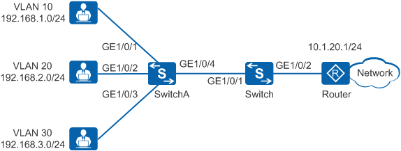
In Figure 1, the company has three departments that belong to VLAN 10, VLAN 20, and VLAN 30, respectively. To ensure security, users in VLAN 10 access only VLAN 20 but not VLAN 30. The three departments need to access the Internet, and there are no other limitations.
Device |
Interface |
VLAN |
Layer 3 Interface |
IP Address |
|---|---|---|---|---|
SwitchA |
GigabitEthernet1/0/1 |
VLAN 10 |
- |
- |
GigabitEthernet1/0/2 |
VLAN 20 |
- |
- |
|
GigabitEthernet1/0/3 |
VLAN 30 |
- |
- |
|
GigabitEthernet1/0/4 |
VLAN 10, VLAN 20, and VLAN 30 |
- |
- |
|
Switch |
GigabitEthernet1/0/1 |
VLAN 10, VLAN 20, and VLAN 30 |
VLANIF 10, VLANIF 20, and VLANIF 30 |
VLANIF 10: 192.168.1.1/24 VLANIF 20: 192.168.2.1/24 VLANIF 30: 192.168.3.1/24 |
GigabitEthernet1/0/2 |
VLAN 40 |
VLANIF 40 |
10.1.20.2/24 |
Configuration Roadmap
- Create VLANs, and configure interfaces and a routing protocol to implement interworking between the company and external network.
- Configure ACL rules on the Switch to define the data flows that are permitted or rejected.
- Configure a traffic classifier on the Switch to classify packets based on the ACL.
- Configure a traffic behavior on the Switch and define the permit action (the ACL defines the data flows that are rejected).
- Configure a traffic policy on the Switch, bind the traffic policy to the traffic classifier and traffic behavior, and apply the traffic policy to GE1/0/1 connected to SwitchA in the inbound direction to implement access control between network segments.
Procedure
- Create VLANs, and configure interfaces and a routing protocol.
# Configure the switch.
<HUAWEI> system-view
[HUAWEI] sysname Switch
[Switch] vlan batch 10 20 30 40  //Create VLAN 10 to VLAN 40.
[Switch] interface gigabitethernet 1/0/1
[Switch-GigabitEthernet1/0/1] port link-type trunk  //Set the link type of the interface to trunk.
[Switch-GigabitEthernet1/0/1] port trunk allow-pass vlan 10 20 30  //Add the interface to VLAN 10, VLAN 20, and VLAN 30.
[Switch-GigabitEthernet1/0/1] quit
[Switch] interface gigabitethernet 1/0/2
[Switch-GigabitEthernet1/0/2] port link-type access  //Set the link type of the interface to access.
[Switch-GigabitEthernet1/0/2] port default vlan 40  //Add the interface to VLAN 40.
[Switch-GigabitEthernet1/0/2] quit
[Switch] interface vlanif 10  //Create a VLANIF interface.
[Switch-Vlanif10] ip address 192.168.1.1 255.255.255.0  //Configure an IP address for the VLANIF interface. The IP address is the gateway address of network segment 192.168.1.0/24.
[Switch-Vlanif10] quit
[Switch] interface vlanif 20
[Switch-Vlanif20] ip address 192.168.2.1 255.255.255.0
[Switch-Vlanif20] quit
[Switch] interface vlanif 30
[Switch-Vlanif30] ip address 192.168.3.1 255.255.255.0
[Switch-Vlanif30] quit
[Switch] interface vlanif 40  //Create a VLANIF interface.
[Switch-Vlanif40] ip address 10.1.20.2 255.255.255.0  //Configure an IP address for the VLANIF interface to connect to the router.
[Switch-Vlanif40] quit
[Switch] ip route-static 0.0.0.0 0 10.1.20.1  //Configure a static route pointing to the external network to implement interworking.
# Configure SwitchA.
<HUAWEI> system-view
[HUAWEI] sysname SwitchA
[SwitchA] vlan batch 10 20 30  //Create VLAN 10 to VLAN 30.
[SwitchA] interface gigabitethernet 1/0/1
[SwitchA-GigabitEthernet1/0/1] port link-type access  //Set the link type of the interface to access.
[SwitchA-GigabitEthernet1/0/1] port default vlan 10  //Add the interface to VLAN 10.
[SwitchA-GigabitEthernet1/0/1] quit
[SwitchA] interface gigabitethernet 1/0/2
[SwitchA-GigabitEthernet1/0/2] port link-type access
[SwitchA-GigabitEthernet1/0/2] port default vlan 20
[SwitchA-GigabitEthernet1/0/2] quit
[SwitchA] interface gigabitethernet 1/0/3
[SwitchA-GigabitEthernet1/0/3] port link-type access
[SwitchA-GigabitEthernet1/0/3] port default vlan 30
[SwitchA-GigabitEthernet1/0/3] quit
[SwitchA] interface gigabitethernet 1/0/4
[SwitchA-GigabitEthernet1/0/4] port link-type trunk  //Set the link type of the interface to trunk.
[SwitchA-GigabitEthernet1/0/4] port trunk allow-pass vlan 10 20 30
[SwitchA-GigabitEthernet1/0/4] quit
# Configure the router.
Configure the IP address of 10.1.20.1/24 for the interface of the router connected to the Switch.
- Configure an ACL.
# Configure ACL rules on the Switch to define the data flows that are permitted or rejected.
[Switch] acl 3000
[Switch-acl-adv-3000] rule deny ip source 192.168.1.0 0.0.0.255 destination 192.168.3.0 0.0.0.255  //Configure an ACL rule to reject data flows from VLAN 10 to VLAN 30.
[Switch-acl-adv-3000] rule permit ip source 192.168.1.0 0.0.0.255 destination 192.168.2.0 0.0.0.255  //Configure an ACL rule to permit data flows from VLAN 10 to VLAN 20.
[Switch-acl-adv-3000] rule permit ip source any  //If there are many internal network segments, configure an ACL to permit any data flows.
[Switch-acl-adv-3000] quit
- Configure a traffic classifier.
# Configure a traffic classifier on the Switch to classify packets based on the ACL.
[Switch] traffic classifier c1 operator and
[Switch-classifier-c1] if-match acl 3000
[Switch-classifier-c1] quit
- Configure a traffic behavior.
# Configure a traffic behavior on the Switch and define the permit action.
[Switch] traffic behavior b1
[Switch-behavior-b1] permit
[Switch-behavior-b1] quit
- Configure a traffic policy and apply the traffic policy to an interface.
# Create a traffic policy on the Switch, bind the traffic behavior and traffic classifier to the traffic policy, and apply the traffic policy to the inbound direction of GE1/0/1 connected to SwitchA.
[Switch] traffic policy p1
[Switch-trafficpolicy-p1] classifier c1 behavior b1
[Switch-trafficpolicy-p1] quit
[Switch] interface gigabitethernet 1/0/1
[Switch-GigabitEthernet1/0/1] traffic-policy p1 inbound
[Switch-GigabitEthernet1/0/1] quit
- Verify the configuration.
# Check the ACL configuration.
[Switch] display acl 3000
Advanced ACL 3000, 3 rules
Acl's step is 5
 rule 5 deny ip source 192.168.1.0 0.0.0.255 destination 192.168.3.0 0.0.0.255 (match-counter 0)
 rule 10 permit ip source 192.168.1.0 0.0.0.255 destination 192.168.2.0 0.0.0.255 (match-counter 0)
 rule 15 permit ip (match-counter 0)
In V200R009 and later versions, (match-counter 0) is not displayed in the display acl command output.
# Check the traffic policy configuration.
[Switch] display traffic policy user-defined p1
  User Defined Traffic Policy Information:
  Policy: p1
   Classifier: c1
    Operator: AND
     Behavior: b1
      Permit
# User devices on network segment 192.168.1.0/24 can ping user devices on network segment 192.168.2.0/24, that is, users in VLAN 10 can access users in VLAN 20.
# User devices on network segment 192.168.1.0/24 cannot ping user devices on network segment 192.168.3.0/24, that is, users in VLAN 10 cannot access users in VLAN 30.
# Users devices on network segments 192.168.1.0/24, 192.168.2.0/24, and 192.168.3.0/24 can ping the IP address 10.1.20.1/24 of the interface on the router, indicating that users of the three departments can access the Internet.
Configuration Files
Switch configuration file
#
sysname Switch
#
vlan batch 10 20 30 40
#
acl number 3000
 rule 5 deny ip source 192.168.1.0 0.0.0.255 destination 192.168.3.0 0.0.0.255
 rule 10 permit ip source 192.168.1.0 0.0.0.255 destination 192.168.2.0 0.0.0.255
 rule 15 permit ip
#
traffic classifier c1 operator and precedence 5
 if-match acl 3000
#
traffic behavior b1
 permit
#
traffic policy p1 match-order config
 classifier c1 behavior b1
#
interface Vlanif10
 ip address 192.168.1.1 255.255.255.0
#
interface Vlanif20
 ip address 192.168.2.1 255.255.255.0
#
interface Vlanif30
 ip address 192.168.3.1 255.255.255.0
#
interface Vlanif40
 ip address 10.1.20.2 255.255.255.0
#
interface GigabitEthernet1/0/1
 port link-type trunk
 port trunk allow-pass vlan 10 20 30
 traffic-policy p1 inbound
#
interface GigabitEthernet1/0/2
 port link-type access
 port default vlan 40
#
ip route-static 0.0.0.0 0.0.0.0 10.1.20.1
#
return
SwitchA configuration file
#
sysname SwitchA
#
vlan batch 10 20 30
#
interface GigabitEthernet1/0/1
 port link-type access
 port default vlan 10
#
interface GigabitEthernet1/0/2
 port link-type access
 port default vlan 20
#
interface GigabitEthernet1/0/3
 port link-type access
 port default vlan 30
#
interface GigabitEthernet1/0/4
 port link-type trunk
 port trunk allow-pass vlan 10 20 30
#
return
Applicable Product Models and Versions
Product |
Product Model |
Software Version |
|---|---|---|
S2700 |
S2752EI |
V100R006C05 |
S2710-SI |
V100R006C05 |
|
S2720-EI |
V200R006C10, V200R009C00, V200R010C00, V200R011C10, V200R012C00, V200R013C00, V200R019C00, V200R019C10 |
|
S2750-EI |
V200R003C00, V200R005C00SPC300, V200R006C00, V200R007C00, V200R008C00, V200R009C00, V200R010C00, V200R011C00, V200R011C10, V200R012C00 |
|
S3700 |
S3700-SI, S3700-EI |
V100R006C05 |
S3700-HI |
V200R001C00 |
|
S5700 |
S5700-LI |
V200R001C00, V200R002C00, V200R003(C00&C02&C10), V200R005C00SPC300, V200R006C00, V200R007C00, V200R008C00, V200R009C00, V200R010C00, V200R011C00, V200R011C10, V200R012C00 |
S5700S-LI |
V200R001C00, V200R002C00, V200R003C00, V200R005C00SPC300, V200R006C00, V200R007C00, V200R008C00, V200R009C00, V200R010C00, V200R011C00, V200R011C10, V200R012C00 |
|
S5700-SI |
V200R001C00, V200R002C00, V200R003C00, V200R005C00 |
|
S5700-EI |
V200R001(C00&C01), V200R002C00, V200R003C00, V200R005(C00&C01&C02&C03) |
|
S5700-HI |
V200R001(C00&C01), V200R002C00, V200R003C00, V200R005(C00SPC500&C01&C02) |
|
S5710-C-LI |
V200R001C00 |
|
S5710-X-LI |
V200R008C00, V200R009C00, V200R010C00, V200R011C00, V200R011C10, V200R012C00 |
|
S5710-EI |
V200R001C00, V200R002C00, V200R003C00, V200R005(C00&C02) |
|
S5710-HI |
V200R003C00, V200R005(C00&C02&C03) |
|
S5720-LI, S5720S-LI |
V200R010C00, V200R011C00, V200R011C10, V200R012(C00&C20), V200R013C00, V200R019C00, V200R019C10 |
|
S5720-SI, S5720S-SI |
V200R008C00, V200R009C00, V200R010C00, V200R011C00, V200R011C10, V200R012C00, V200R013C00, V200R019C00, V200R019C10 |
|
S5720I-SI |
V200R012C00, V200R013C00, V200R019C00, V200R019C10 |
|
S5720-EI |
V200R007C00, V200R008C00, V200R009C00, V200R010C00, V200R011C00, V200R011C10, V200R012C00, V200R013C00, V200R019C00, V200R019C10 |
|
S5720-HI |
V200R006C00, V200R007(C00&C10), V200R008C00, V200R009C00, V200R010C00, V200R011C00, V200R011C10, V200R012C00, V200R013C00, V200R019C00, V200R019C10 |
|
S5730-HI |
V200R012C00, V200R013C00, V200R019C00, V200R019C10 |
|
S5730-SI |
V200R011C10, V200R012C00, V200R013C00, V200R019C00, V200R019C10 |
|
S5730S-EI |
V200R011C10, V200R012C00, V200R013C00, V200R019C00, V200R019C10 |
|
S5731-H |
V200R013C02, V200R019C00, V200R019C10 |
|
S5731-S, S5731S-S |
V200R019C00, V200R019C10 |
|
S5731S-H |
V200R019C00, V200R019C10 |
|
S5732-H |
V200R019C00, V200R019C10 |
|
S5735-L, S5735S-L |
V200R019C00, V200R019C10 |
|
S5735S-L-M |
V200R019C00, V200R019C10 |
|
S5735-S, S5735S-S |
V200R019C00, V200R019C10 |
|
S5700 |
S5735-S-I |
V200R019C10 |
S6700 |
S6700-EI |
V200R001(C00&C01), V200R002C00, V200R003C00, V200R005(C00&C01&C02) |
S6720-LI, S6720S-LI |
V200R011C00, V200R011C10, V200R012C00, V200R013C00, V200R019C00, V200R019C10 |
|
S6720-SI, S6720S-SI |
V200R011C00, V200R011C10, V200R012C00, V200R013C00, V200R019C00, V200R019C10 |
|
S6720-EI |
V200R008C00, V200R009C00, V200R010C00, V200R011C00, V200R011C10, V200R012C00, V200R013C00, V200R019C00, V200R019C10 |
|
S6720S-EI |
V200R009C00, V200R010C00, V200R011C00, V200R011C10, V200R012C00, V200R013C00, V200R019C00, V200R019C10 |
|
S6720-HI |
V200R012C00, V200R013C00, V200R019C00, V200R019C10 |
|
S6730-H |
V200R013C02, V200R019C00, V200R019C10 |
|
S6730-S, S6730S-S |
V200R019C00, V200R019C10 |
|
S6730S-H |
V200R019C10 |
|
S7700 |
S7703, S7706, S7712 |
V200R001(C00&C01), V200R002C00, V200R003C00, V200R005C00, V200R006C00, V200R007C00, V200R008C00, V200R009C00, V200R010C00, V200R011C10, V200R012C00, V200R013C00, V200R013C02, V200R019C00, V200R019C10 |
S7703 PoE |
V200R013C00, V200R019C00, V200R019C10 |
|
S7706 PoE |
V200R013C00, V200R019C00, V200R019C10 |
|
S9700 |
S9703, S9706, S9712 |
V200R001(C00&C01), V200R002C00, V200R003C00, V200R005C00, V200R006C00, V200R007(C00&C10), V200R008C00, V200R009C00, V200R010C00, V200R011C10, V200R012C00, V200R013C00 |