Example for Configuring Basic RIP Functions
Networking Requirements
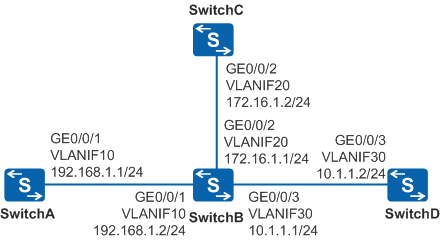
In Figure 1, SwitchA, SwitchB, SwitchC, and SwitchD are located on a small-sized network and need to communicate with each other.
Configuration Roadmap
RIP-2 is recommended if the network size is small. The configuration roadmap is as follows:
Configure VLAN and IP address for each interface to ensure network reachability.
Enable RIP on each switch to implement network connections between processes.
Configure RIP-2 on each switch to improve RIP performance.
Procedure
- Configure VLANs and add interfaces to the
VLANs. The configurations of SwitchB, SwitchC,
and SwitchD are similar
to the configuration of SwitchA, and are not mentioned here.
<HUAWEI> system-view
[HUAWEI] sysname SwitchA
[SwitchA] vlan 10
[SwitchA-vlan10] quit
[SwitchA] interface gigabitethernet 0/0/1
[SwitchA-GigabitEthernet0/0/1] port link-type trunk
[SwitchA-GigabitEthernet0/0/1] port trunk allow-pass vlan 10
[SwitchA-GigabitEthernet0/0/1] quit
- Configure an IP address to each VLANIF interface. The configurations
of SwitchB, SwitchC, and SwitchD are similar to the configuration
of SwitchA, and are not
mentioned here.
[SwitchA] interface vlanif 10
[SwitchA-Vlanif10] ip address 192.168.1.1 24
[SwitchA-Vlanif10] quit
- Configure basic RIP functions.
# Configure SwitchA.
[SwitchA] rip
[SwitchA-rip-1] network 192.168.1.0
[SwitchA-rip-1] quit
# Configure SwitchB.
[SwitchB] rip
[SwitchB-rip-1] network 192.168.1.0
[SwitchB-rip-1] network 172.16.0.0
[SwitchB-rip-1] network 10.0.0.0
[SwitchB-rip-1] quit
# Configure SwitchC.
[SwitchC] rip
[SwitchC-rip-1] network 172.16.0.0
[SwitchC-rip-1] quit
# Configure SwitchD.
[SwitchD] rip
[SwitchD-rip-1] network 10.0.0.0
[SwitchD-rip-1] quit
# Check the RIP routing table of SwitchA.
[SwitchA] display rip 1 route
 Route Flags : R - RIP
              A - Aging, G - Garbage-collect
----------------------------------------------------------------------------
 Peer 192.168.1.2  on Vlanif10
      Destination/Mask        Nexthop     Cost   Tag     Flags   Sec
       172.16.0.0/16       192.168.1.2      1    0        RA      14
         10.0.0.0/8        192.168.1.2      1    0        RA      14
The command output shows that the routes advertised by RIP-1 use natural masks.
- Configure the RIP version.
# Configure RIP-2 on SwitchA.
[SwitchA] rip
[SwitchA-rip-1] version 2
[SwitchA-rip-1] quit
# Configure RIP-2 on SwitchB.
[SwitchB] rip
[SwitchB-rip-1] version 2
[SwitchB-rip-1] quit
# Configure RIP-2 on SwitchC.
[SwitchC] rip
[SwitchC-rip-1] version 2
[SwitchC-rip-1] quit
# Configure RIP-2 on SwitchD.
[SwitchD] rip
[SwitchD-rip-1] version 2
[SwitchD-rip-1] quit
- Verify the configuration.
# Check the RIP routing table of SwitchA.
[SwitchA] display rip 1 route
Route Flags : R - RIP
             A - Aging, G - Garbage-collect
----------------------------------------------------------------------------
 Peer 192.168.1.2  on Vlanif10
      Destination/Mask        Nexthop       Cost   Tag     Flags   Sec
       172.16.1.0/24         192.168.1.2      1    0        RA      32
         10.1.1.0/24         192.168.1.2      1    0        RA      32
From the routing table, you can find that the routes advertised by RIP-2 contain more accurate subnet masks.
Configuration Files
SwitchA configuration file
#
sysname SwitchA
#
vlan batch 10
#
interface Vlanif10
 ip address 192.168.1.1 255.255.255.0
#
interface GigabitEthernet0/0/1
 port link-type trunk
 port trunk allow-pass vlan 10
#
rip 1
 version 2
 network 192.168.1.0
#
return
SwitchB configuration file
#
sysname SwitchB
#
vlan batch 10 20 30
#
interface Vlanif10
 ip address 192.168.1.2 255.255.255.0
#
interface Vlanif20
 ip address 172.16.1.1 255.255.255.0
#
interface Vlanif30
 ip address 10.1.1.1 255.255.255.0
#
interface GigabitEthernet0/0/1
 port link-type trunk
 port trunk allow-pass vlan 10
#
interface GigabitEthernet0/0/2
 port link-type trunk
 port trunk allow-pass vlan 20
#
interface GigabitEthernet0/0/3
 port link-type trunk
 port trunk allow-pass vlan 30
#
rip 1
 version 2
 network 192.168.1.0
 network 172.16.0.0
 network 10.0.0.0
#
return
SwitchC configuration file
#
sysname SwitchC
#
vlan batch 20
#
interface Vlanif20
 ip address 172.16.1.2 255.255.255.0
#
interface GigabitEthernet0/0/2
 port link-type trunk
 port trunk allow-pass vlan 20
#
rip 1
 version 2
 network 172.16.0.0
#
return
SwitchD configuration file
#
sysname SwitchD
#
vlan batch 30
#
interface Vlanif30
 ip address 10.1.1.2 255.255.255.0
#
interface GigabitEthernet0/0/3
 port link-type trunk
 port trunk allow-pass vlan 30
#
rip 1
 version 2
 network 10.0.0.0
#
return