Example for Configuring RIP to Import Routes
Networking Requirements
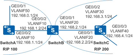
In Figure 1, two RIP processes, RIP 100 and RIP 200, run on SwitchB. SwitchA needs to communicate with network segment 192.168.3.0/24.
Configuration Roadmap
The configuration roadmap is as follows:
Enable RIP on each switch to implement network connections between processes.
Import routes between RIP 100 and RIP 200 on SwitchB and set the default metric of routes imported from RIP 200 to 3.
Configure an ACL on SwitchB to filter route 192.168.4.0/24 imported from RIP 200 so that SwitchA can only communicate with network segment 192.168.3.0/24.
Procedure
- Configure VLANs and add interfaces to the VLANs. The configurations
of Switch B, and Switch C are similar to the configuration
of Switch A, and are
not mentioned here.
<HUAWEI> system-view
[HUAWEI] sysname SwitchA
[SwitchA] vlan batch 10 50
[SwitchA] interface gigabitethernet 0/0/1
[SwitchA-GigabitEthernet0/0/1] port link-type trunk
[SwitchA-GigabitEthernet0/0/1] port trunk allow-pass vlan 50
[SwitchA-GigabitEthernet0/0/1] quit
[SwitchA] interface gigabitethernet 0/0/2
[SwitchA-GigabitEthernet0/0/2] port link-type trunk
[SwitchA-GigabitEthernet0/0/2] port trunk allow-pass vlan 10
[SwitchA-GigabitEthernet0/0/2] quit
- Configure an IP address to each VLANIF interface. The configurations
of Switch B, and Switch C are similar to the configuration
of Switch A, and are
not mentioned here.
[SwitchA] interface vlanif 10
[SwitchA-Vlanif10] ip address 192.168.1.1 24
[SwitchA-Vlanif10] quit
[SwitchA] interface vlanif 50
[SwitchA-Vlanif50] ip address 192.168.0.1 24
[SwitchA-Vlanif50] quit
- Configure basic RIP functions.
# Enable RIP 100 on SwitchA.
[SwitchA] rip 100
[SwitchA-rip-100] network 192.168.0.0
[SwitchA-rip-100] network 192.168.1.0
[SwitchA-rip-100] quit
# Enable RIP 100 and RIP 200 on SwitchB.
[SwitchB] rip 100
[SwitchB-rip-100] network 192.168.1.0
[SwitchB-rip-100] quit
[SwitchB] rip 200
[SwitchB-rip-200] network 192.168.2.0
[SwitchB-rip-200] quit
# Enable RIP 200 on SwitchC.
[SwitchC] rip 200
[SwitchC-rip-200] network 192.168.2.0
[SwitchC-rip-200] network 192.168.3.0
[SwitchC-rip-200] network 192.168.4.0
[SwitchC-rip-200] quit
# View the routing table on SwitchA.
[SwitchA] display ip routing-table
Route Flags: R - relay, D - download to fib, T - to vpn-instance
------------------------------------------------------------------------------
Routing Tables: Public
         Destinations : 6       Routes : 6

Destination/Mask    Proto  Pre  Cost   Flags    NextHop        Interface

      127.0.0.0/8   Direct 0    0        D      127.0.0.1      InLoopBack0
      127.0.0.1/32  Direct 0    0        D      127.0.0.1      InLoopBack0
    192.168.0.0/24  Direct 0    0        D      192.168.0.1    Vlanif50
    192.168.0.1/32  Direct 0    0        D      127.0.0.1      Vlanif50
    192.168.1.0/24  Direct 0    0        D      192.168.1.1    Vlanif10
    192.168.1.1/32  Direct 0    0        D      127.0.0.1      Vlanif10
The routing table of SwitchA does not contain the routes imported from other processes.
- Configure RIP to import external routes.
# On SwitchB, set the default metric of imported routes to 3 in RIP 100 and configure the two RIP processes to import routes into each other's routing table.
[SwitchB] rip 100
[SwitchB-rip-100] default-cost 3
[SwitchB-rip-100] import-route rip 200
[SwitchB-rip-100] quit
[SwitchB] rip 200
[SwitchB-rip-200] import-route rip 100
[SwitchB-rip-200] quit
# View the routing table of SwitchA after the routes are imported.
[SwitchA] display ip routing-table
Route Flags: R - relay, D - download to fib, T - to vpn-instance
------------------------------------------------------------------------------
Routing Tables: Public
         Destinations : 9       Routes : 9

Destination/Mask    Proto  Pre  Cost   Flags    NextHop         Interface

      127.0.0.0/8   Direct 0    0       D         127.0.0.1       InLoopBack0
      127.0.0.1/32  Direct 0    0       D         127.0.0.1       InLoopBack0
    192.168.0.0/24  Direct 0    0       D         192.168.0.1     Vlanif50
    192.168.0.1/32  Direct 0    0       D         127.0.0.1       Vlanif50
    192.168.1.0/24  Direct 0    0       D         192.168.1.1     Vlanif10
    192.168.1.1/32  Direct 0    0       D         127.0.0.1       Vlanif10
    192.168.2.0/24  RIP    100  4       D         192.168.1.2     Vlanif10
    192.168.3.0/24  RIP    100  4       D         192.168.1.2     Vlanif10
    192.168.4.0/24  RIP    100  4       D         192.168.1.2     Vlanif10
The routing table of SwitchA contains routes 192.168.2.0/24, 192.168.3.0/24, and 192.168.4.0/24, which are learned by RIP 200 on SwitchB.
- Configure RIP to filter imported routes.
# Configure an ACL on SwitchB and add a rule to the ACL. The rule denies the packets sent from 192.168.4.0/24.
[SwitchB] acl 2000
[SwitchB-acl-basic-2000] rule deny source 192.168.4.0 0.0.0.255
[SwitchB-acl-basic-2000] rule permit
[SwitchB-acl-basic-2000] quit
# Configure SwitchB to filter route 192.168.4.0/24 imported from RIP 200.
[SwitchB] rip 100
[SwitchB-rip-100] filter-policy 2000 export
[SwitchB-rip-100] quit
- Verify the configuration.
# Display the RIP routing table of SwitchA after the routes are filtered.
[SwitchA] display ip routing-table
Route Flags: R - relay, D - download to fib, T - to vpn-instance
------------------------------------------------------------------------------
Routing Tables: Public
         Destinations : 8        Routes : 8

Destination/Mask    Proto  Pre  Cost   Flags    NextHop         Interface

      127.0.0.0/8   Direct 0    0       D         127.0.0.1       InLoopBack0
      127.0.0.1/32  Direct 0    0       D         127.0.0.1       InLoopBack0
    192.168.0.0/24  Direct 0    0       D         192.168.0.1     Vlanif50
    192.168.0.1/32  Direct 0    0       D         127.0.0.1       Vlanif50
    192.168.1.0/24  Direct 0    0       D         192.168.1.1     Vlanif10
    192.168.1.1/32  Direct 0    0       D         127.0.0.1       Vlanif10
    192.168.2.0/24  RIP    100  4       D         192.168.1.2     Vlanif10
    192.168.3.0/24  RIP    100  4       D         192.168.1.2     Vlanif10
The routing table of SwitchA does not contain the route originating from 192.168.4.0/24.
Configuration Files
SwitchA configuration file
#
sysname SwitchA
#
vlan batch 10 50
#
interface Vlanif10
 ip address 192.168.1.1 255.255.255.0
#
interface Vlanif50
 ip address 192.168.0.1 255.255.255.0
#
interface GigabitEthernet0/0/1
 port link-type trunk
 port trunk allow-pass vlan 50
#
interface GigabitEthernet0/0/2
 port link-type trunk
 port trunk allow-pass vlan 10
#
rip 100
 network 192.168.0.0
 network 192.168.1.0
#
return
SwitchB configuration file
#
sysname SwitchB
#
vlan batch 10 20
#
acl number 2000
 rule 5 deny source 192.168.4.0 0.0.0.255
 rule 10 permit
#
interface Vlanif10
 ip address 192.168.1.2 255.255.255.0
#
interface Vlanif20
 ip address 192.168.2.1 255.255.255.0
#
interface GigabitEthernet0/0/1
 port link-type trunk
 port trunk allow-pass vlan 20
#
interface GigabitEthernet0/0/2
 port link-type trunk
 port trunk allow-pass vlan 10
#
rip 100
 default-cost 3
 network 192.168.1.0
 filter-policy 2000 export
 import-route rip 200
#
rip 200
 network 192.168.2.0
 import-route rip 100
#
return
SwitchC configuration file
#
sysname SwitchC
#
vlan batch 20 30 40
#
interface Vlanif20
 ip address 192.168.2.2 255.255.255.0
#
interface Vlanif30
 ip address 192.168.3.1 255.255.255.0
#
interface Vlanif40
 ip address 192.168.4.1 255.255.255.0
#
interface GigabitEthernet0/0/1
 port link-type trunk
 port trunk allow-pass vlan 20
#
interface GigabitEthernet0/0/2
 port link-type trunk
 port trunk allow-pass vlan 30
#
interface GigabitEthernet0/0/3
 port link-type trunk
 port trunk allow-pass vlan 40
#
rip 200
 network 192.168.2.0
 network 192.168.3.0
 network 192.168.4.0
#
return