Example for Configuring Tangent RRPP Rings
Networking Requirements
Ethernet network uses two-layer rings:
One layer is the aggregation layer between aggregation devices PE-AGGs, such as RRPP Domain 1 in Figure 1.
The other layer is the access layer between PE-AGGs and UPEs, such as RRPP Domain 2 and RRPP Domain 3 in Figure 1.

As shown in Figure 1, the network is required to prevent loops when the ring is complete and implement fast convergence to rapidly restore communication between nodes on the ring when the ring fails. RRPP can meet this requirement. RRPP supports multiple rings. You can configure the aggregation layer and access layer as RRPP rings and the two rings are tangent, simplifying the network configuration.
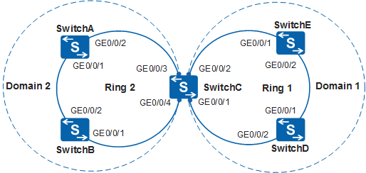
As shown in Figure 2, SwitchE, SwitchD, SwitchC, SwitchA, and SwitchB map PE-AGG1, PE-AGG2, PE-AGG3, UPE 1, and UPE 2 in Figure 1 respectively. Figure 2 is used as an example to describe how to configure tangent RRPP rings with a single instance.
Configuration Roadmap
The configuration roadmap is as follows:
Create different RRPP domains and control VLANs to configure an RRPP ring.
Map the VLANs that need to pass through Ring 1 to Instance 1, including data VLANs and control VLANs to configure protected VLANs.
Map the VLANs that need to pass through Ring 2 to Instance 2, including data VLANs and control VLANs to configure protected VLANs.
Configure timers for different RRPP domains.

You can configure two timers for tangent points because two tangent rings locate in different domains.
Configure interfaces to be added to the RRPP domain on the devices so that data can pass through the interfaces. Disable protocols that conflict with RRPP, such as STP.
- Configure protected VLANs and create RRPP rings in RRPP domains.
Configure Ring 2 in Domain 2 on SwitchA, SwitchB, and SwitchC.
Configure Ring 1 in Domain 1 on SwitchC, SwitchD, and SwitchE.
Configure SwitchA as the master node on Ring 2, and configure SwitchB and SwitchC as transit nodes on Ring 2.
Configure SwitchE as the master node on Ring 1, and configure SwitchC and SwitchD as transit nodes on Ring 1.
Enable the RRPP ring and RRPP protocol on devices to make RRPP take effect.
Procedure
- Configure instance 2, and map it to the data VLANs and
control VLANs allowed by the RRPP interface.
# Configure SwitchA. The configurations of SwitchB, SwitchC, SwitchD, and SwitchE are similar to the configuration of SwitchA and not mentioned here. For details, see the configuration files.
<HUAWEI> system-view
[HUAWEI] sysname SwitchA
[SwitchA] stp region-configuration
[SwitchA-mst-region] instance 2 vlan 20 to 21
[SwitchA-mst-region] active region-configuration
[SwitchA-mst-region] quit
- Create RRPP domains and configure control VLANs and protected
VLANs in the domains.
# Configure SwitchE. The configurations of SwitchA, SwitchB, SwitchC, and SwitchD are similar to the configuration of SwitchE and not mentioned here. For details, see the configuration files.
[SwitchE] rrpp domain 1
[SwitchE-rrpp-domain-region1] control-vlan 10
[SwitchE-rrpp-domain-region1] protected-vlan reference-instance 1
[SwitchE-rrpp-domain-region1] quit
- Set the timers of RRPP domains.
# Set the timers for SwitchE, the master node on Ring 1.
[SwitchE] rrpp domain 1
[SwitchE-rrpp-domain-region1] timer hello-timer 2 fail-timer 7
[SwitchE-rrpp-domain-region1] quit
# Set the timers for SwitchD, the transit node on Ring 1.
[SwitchD] rrpp domain 1
[SwitchD-rrpp-domain-region1] timer hello-timer 2 fail-timer 7
[SwitchD-rrpp-domain-region1] quit
# Set the timers for SwitchC, the transit node on Ring 1.
[SwitchC] rrpp domain 1
[SwitchC-rrpp-domain-region1] timer hello-timer 2 fail-timer 7
[SwitchC-rrpp-domain-region1] quit
# Set the timers for SwitchA, the master node on Ring 2.
[SwitchA] rrpp domain 2
[SwitchA-rrpp-domain-region2] timer hello-timer 3 fail-timer 10
[SwitchA-rrpp-domain-region2] quit
# Set the timers for SwitchB, the transit node on Ring 2.
[SwitchB] rrpp domain 2
[SwitchB-rrpp-domain-region2] timer hello-timer 3 fail-timer 10
[SwitchB-rrpp-domain-region2] quit
# Set the timers for SwitchC, the transit node on Ring 2.
[SwitchC] rrpp domain 2
[SwitchC-rrpp-domain-region2] timer hello-timer 3 fail-timer 10
[SwitchC-rrpp-domain-region2] quit
- Configure the interfaces to be added to the RRPP ring as
trunk interfaces and disable STP on the interfaces.
# Configure SwitchA. The configurations of SwitchB, SwitchC, SwitchD, and SwitchE are similar to the configuration of SwitchA and not mentioned here. For details, see the configuration files.
[SwitchA] interface gigabitethernet 0/0/1
[SwitchA-GigabitEthernet0/0/1] port link-type trunk
[SwitchA-GigabitEthernet0/0/1] undo port trunk allow-pass vlan 1
[SwitchA-GigabitEthernet0/0/1] stp disable
[SwitchA-GigabitEthernet0/0/1] quit
[SwitchA] interface gigabitethernet 0/0/2
[SwitchA-GigabitEthernet0/0/2] port link-type trunk
[SwitchA-GigabitEthernet0/0/2] undo port trunk allow-pass vlan 1
[SwitchA-GigabitEthernet0/0/2] stp disable
[SwitchA-GigabitEthernet0/0/2] quit
- Create and enable RRPP rings.
Configure nodes on Ring 2.
# Configure SwitchA as the master node on Ring 2 and specify the primary and secondary interfaces.
[SwitchA] rrpp domain 2
[SwitchA-rrpp-domain-region2] ring 2 node-mode master primary-port gigabitethernet 0/0/1 secondary-port gigabitethernet 0/0/2 level 0
[SwitchA-rrpp-domain-region2] ring 2 enable
[SwitchA-rrpp-domain-region2] quit
# Configure SwitchB as a transit node on Ring 2 (major ring) and specify the primary and secondary interfaces.
[SwitchB] rrpp domain 2
[SwitchB-rrpp-domain-region2] ring 2 node-mode transit primary-port gigabitethernet 0/0/1 secondary-port gigabitethernet 0/0/2 level 0
[SwitchB-rrpp-domain-region2] ring 2 enable
[SwitchB-rrpp-domain-region2] quit
# Configure SwitchC as a transit node on Ring 2 and specify the primary and secondary interfaces.
[SwitchC] rrpp domain 2
[SwitchC-rrpp-domain-region2] ring 2 node-mode transit primary-port gigabitethernet 0/0/3 secondary-port gigabitethernet 0/0/4 level 0
[SwitchC-rrpp-domain-region2] ring 2 enable
[SwitchC-rrpp-domain-region2] quit
Configure nodes on Ring 1. The configuration procedure is as follows:
# Configure SwitchE as the master node on Ring 1 (major ring) and specify the primary and secondary interfaces.
[SwitchE] rrpp domain 1
[SwitchE-rrpp-domain-region1] ring 1 node-mode master primary-port gigabitethernet 0/0/1 secondary-port gigabitethernet 0/0/2 level 0
[SwitchE-rrpp-domain-region1] ring 1 enable
[SwitchE-rrpp-domain-region1] quit
# Configure SwitchC as a transit node on Ring 1 and specify the primary and secondary interfaces.
[SwitchC] rrpp domain 1
[SwitchC-rrpp-domain-region1] ring 1 node-mode transit primary-port gigabitethernet 0/0/1 secondary-port gigabitethernet 0/0/2 level 0
[SwitchC-rrpp-domain-region1] ring 1 enable
[SwitchC-rrpp-domain-region1] quit
# Configure SwitchD as a transit node on Ring 1 and specify the primary and secondary interfaces.
[SwitchD] rrpp domain 1
[SwitchD-rrpp-domain-region1] ring 1 node-mode transit primary-port gigabitethernet 0/0/1 secondary-port gigabitethernet 0/0/2 level 0
[SwitchD-rrpp-domain-region1] ring 1 enable
[SwitchD-rrpp-domain-region1] quit
- Enable RRPP.
# Configure SwitchA. The configurations on SwitchB, SwitchC, SwitchD, and SwitchE are the same as that of SwitchA and not mentioned here. For details, see the configuration files.
[SwitchA] rrpp enable - Verify the configuration.
After the preceding configurations are complete and the network topology becomes stable, perform the following operations to verify the configuration. The tangent point SwitchC is used as an example.
# Run the display rrpp brief command on SwitchC. The command output is as follows:
[SwitchC] display rrpp brief
Abbreviations for Switch Node Mode :
M - Master , T - Transit , E - Edge , A - Assistant-Edge

RRPP Protocol Status: Enable
RRPP Working Mode: HW
RRPP Linkup Delay Timer: 0 sec (0 sec default)
Number of RRPP Domains: 2

Domain Index   : 1
Control VLAN   : major 10    sub 11
Protected VLAN : Reference Instance 1
Hello Timer    : 2 sec(default is 1 sec)  Fail Timer : 7 sec(default is 6 sec)

Ring  Ring   Node  Primary/Common           Secondary/Edge           Is
ID    Level  Mode  Port                     Port                     Enabled
----------------------------------------------------------------------------
1     0      T     GigabitEthernet0/0/1     GigabitEthernet0/0/2     Yes

Domain Index   : 2
Control VLAN   : major 20    sub 21
Protected VLAN : Reference Instance 2
Hello Timer    : 3 sec(default is 1 sec)  Fail Timer : 10 sec(default is 6 sec)

Ring  Ring   Node  Primary/Common           Secondary/Edge           Is
ID    Level  Mode  Port                     Port                     Enabled
----------------------------------------------------------------------------
2     0      T     GigabitEthernet0/0/3    GigabitEthernet0/0/4     Yes
The command output shows that RRPP is enabled on SwitchC. In Domain 1, the major control VLAN is VLAN 10, and the sub-control VLAN is VLAN 11. SwitchC is the transit node on the major ring, with GigabitEthernet0/0/1 as the primary interface and GigabitEthernet0/0/2 as the secondary interface.
In Domain 2, the major control VLAN is VLAN 20, and the sub-control VLAN is VLAN 21. SwitchC is a transit node on Ring 2. GigabitEthernet0/0/3 is the primary interface and GigabitEthernet0/0/4 is the secondary interface.
Run the display rrpp verbose domain command on SwitchC. The command output is as follows:
# Display detailed information about Domain 1 on SwitchC.
[SwitchC] display rrpp verbose domain 1
Domain Index  : 1
Control VLAN   : major 10    sub 11
Protected VLAN : Reference Instance 1
Hello Timer    : 2 sec(default is 1 sec)  Fail Timer : 7 sec(default is 6 sec)

RRPP Ring      : 1
Ring Level     : 0
Node Mode      : Transit
Ring State     : LinkUp
Is Enabled     : Enable                       Is Active: Yes
Primary port   : GigabitEthernet0/0/1         Port status: UP
Secondary port : GigabitEthernet0/0/2         Port status: UP
# Display detailed information about Domain 2 on SwitchC.
[SwitchC] display rrpp verbose domain 2
Domain Index   : 2
Control VLAN   : major 20    sub 21
Protected VLAN : Reference Instance 2
Hello Timer    : 3 sec(default is 1 sec)  Fail Timer : 10 sec(default is 6 sec)

RRPP Ring      : 2
Ring Level     : 0
Node Mode      : Transit
Ring State     : LinkUp
Is Enabled     : Enable                       Is Active: Yes
Primary port   : GigabitEthernet0/0/3         Port status: UP
Secondary port : GigabitEthernet0/0/4         Port status: UP
Configuration Files
SwitchA configuration file
#
sysname SwitchA
#
vlan batch 20 to 21
#
rrpp enable
#
stp region-configuration
 instance 2 vlan 20 to 21
 active region-configuration
#
rrpp domain 2
 control-vlan 20
 protected-vlan reference-instance 2
 timer hello-timer 3 fail-timer 10
 ring 2 node-mode master primary-port GigabitEthernet0/0/1 secondary-port GigabitEthernet0/0/2 level 0
 ring 2 enable
#
interface GigabitEthernet0/0/1
 port link-type trunk
 undo port trunk allow-pass vlan 1
 port trunk allow-pass vlan 20 to 21
 stp disable
#
interface GigabitEthernet0/0/2
 port link-type trunk
 undo port trunk allow-pass vlan 1
 port trunk allow-pass vlan 20 to 21
 stp disable
#
return
SwitchB configuration file
#
sysname SwitchB
#
vlan batch 20 to 21
#
rrpp enable
#
stp region-configuration
 instance 2 vlan 20 to 21
 active region-configuration
#
rrpp domain 2
 control-vlan 20
 protected-vlan reference-instance 2
 timer hello-timer 3 fail-timer 10
 ring 2 node-mode transit primary-port GigabitEthernet0/0/1 secondary-port GigabitEthernet0/0/2 level 0
 ring 2 enable
#
interface GigabitEthernet0/0/1
 port link-type trunk
 undo port trunk allow-pass vlan 1
 port trunk allow-pass vlan 20 to 21
 stp disable
#
interface GigabitEthernet0/0/2
 port link-type trunk
 undo port trunk allow-pass vlan 1
 port trunk allow-pass vlan 20 to 21
 stp disable
#
return
SwitchC configuration file
#
sysname SwitchC
#
vlan batch 10 to 11 20 to 21
#
rrpp enable
#
stp region-configuration
 instance 1 vlan 10 to 11
 instance 2 vlan 20 to 21
 active region-configuration
#
rrpp domain 1
 control-vlan 10
 protected-vlan reference-instance 1
 timer hello-timer 2 fail-timer 7
 ring 1 node-mode transit primary-port GigabitEthernet0/0/1 secondary-port GigabitEthernet0/0/2 level 0
 ring 1 enable
rrpp domain 2
 control-vlan 20
 protected-vlan reference-instance 2
 timer hello-timer 3 fail-timer 10
 ring 2 node-mode transit primary-port GigabitEthernet0/0/3 secondary-port GigabitEthernet0/0/4 level 0
 ring 2 enable
#
interface GigabitEthernet0/0/1
 port link-type trunk
 undo port trunk allow-pass vlan 1
 port trunk allow-pass vlan 10 to 11
 stp disable
#
interface GigabitEthernet0/0/2
 port link-type trunk
 undo port trunk allow-pass vlan 1
 port trunk allow-pass vlan 10 to 11
 stp disable
#
interface GigabitEthernet0/0/3
 port link-type trunk
 undo port trunk allow-pass vlan 1
 port trunk allow-pass vlan 20 to 21
 stp disable
#
interface GigabitEthernet0/0/4
 port link-type trunk
 undo port trunk allow-pass vlan 1
 port trunk allow-pass vlan 20 to 21
 stp disable
#
return
SwitchD configuration file
#
sysname SwitchD
#
vlan batch 10 to 11
#
rrpp enable
#
stp region-configuration
 instance 1 vlan 10 to 11
 active region-configuration
#
rrpp domain 1
 control-vlan 10
 protected-vlan reference-instance 1
 timer hello-timer 2 fail-timer 7
 ring 1 node-mode transit primary-port GigabitEthernet0/0/1 secondary-port GigabitEthernet0/0/2 level 0
 ring 1 enable
#
interface GigabitEthernet0/0/1
 port link-type trunk
 undo port trunk allow-pass vlan 1
 port trunk allow-pass vlan 10 to 11
 stp disable
#
interface GigabitEthernet0/0/2
 port link-type trunk
 undo port trunk allow-pass vlan 1
 port trunk allow-pass vlan 10 to 11
 stp disable
#
return
SwitchE configuration file
#
sysname SwitchE
#
vlan batch 10 to 11
#
rrpp enable
#
stp region-configuration
 instance 1 vlan 10 to 11
 active region-configuration
#
rrpp domain 1
 control-vlan 10
 protected-vlan reference-instance 1
 timer hello-timer 2 fail-timer 7
 ring 1 node-mode master primary-port GigabitEthernet0/0/1 secondary-port GigabitEthernet0/0/2 level 0
 ring 1 enable
#
interface GigabitEthernet0/0/1
 port link-type trunk
 undo port trunk allow-pass vlan 1
 port trunk allow-pass vlan 10 to 11
 stp disable
#
interface GigabitEthernet0/0/2
 port link-type trunk
 undo port trunk allow-pass vlan 1
 port trunk allow-pass vlan 10 to 11
 stp disable
#
return