Example for Configuring Inter-AS Seamless MPLS
Networking Requirements
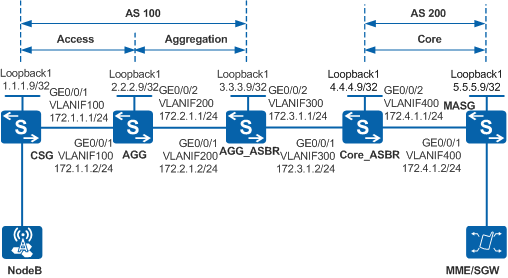
In Figure 1, the access, aggregation, and core layers belong to different ASs. To enable the base station NodeB to communicate with the MME/SGW and provide the VPN service to the MME/SGW, the customer wants to use MPLS at the access layer, so that a complete LSP can be set up over the three layers. To provide an end-to-end service and simplify service configuration and network management, inter-AS seamless MPLS can be configured on the network.
Configuration Roadmap
The configuration roadmap is as follows:
Configure IGP protocols at the access, aggregation, and core layers to implement network connectivity at each layer.
Configure MPLS and MPLS LDP on each device and establish an MPLS LSP.
Establish IBGP peer relationships at each layer and enable devices to exchange labeled routes.
Configure an EBGP peer relationship between each pair of an AGG_ASBR and Core_ASBR and enable these devices to exchange labeled routes across ASs.
Configure each AGG as an RR to help the CSG and MASG obtain the route destined for each other's loopback interface.
Configure a routing policy to control label distribution for a BGP LSP to be established on each device. The ingress node on the BGP LSP needs to distribute an MPLS label to the route advertised to a downstream node. If a transit node on the BGP LSP receives a labeled IPv4 route from its upstream node, the transit node must re-distribute an MPLS label to the labeled IPv4 route before advertising the route to a downstream node.
Procedure
- On the devices, create a VLAN and a VLANIF interface, assign an IP address to the VLANIF interface, and add a physical interface to the VLAN.
# Configure the CSG. The configurations of the AGG, AGG_ASBR, Core_ASBR, and MASG are similar to that of the CSG, and are not mentioned here.
<HUAWEI> system-view
[HUAWEI] sysname CSG
[CSG] interface loopback 1
[CSG-LoopBack1] ip address 1.1.1.9 32
[CSG-LoopBack1] quit
[CSG] vlan batch 100
[CSG] interface vlanif 100
[CSG-Vlanif100] ip address 172.1.1.1 24
[CSG-Vlanif100] quit
[CSG] interface gigabitethernet0/0/1
[CSG-GigabitEthernet0/0/1] port link-type trunk
[CSG-GigabitEthernet0/0/1] port trunk allow-pass vlan 100
[CSG-GigabitEthernet0/0/1] quit
- Enable OSPF or IS-IS to advertise routes on network segments where each node locates and routes represented by LSR IDs.
# Configure the CSG.
[CSG] ospf 1
[CSG-ospf-1] area 0
[CSG-ospf-1-area-0.0.0.0] network 1.1.1.9 0.0.0.0
[CSG-ospf-1-area-0.0.0.0] network 172.1.1.0 0.0.0.255
[CSG-ospf-1-area-0.0.0.0] quit
[CSG-ospf-1] quit
# Configure the AGG.
[AGG] ospf 1
[AGG-ospf-1] area 0
[AGG-ospf-1-area-0.0.0.0] network 2.2.2.9 0.0.0.0
[AGG-ospf-1-area-0.0.0.0] network 172.1.1.0 0.0.0.255
[AGG-ospf-1-area-0.0.0.0] quit
[AGG-ospf-1] quit
[AGG] isis 1
[AGG-isis-1] network-entity 10.0000.0000.0000.0010.00
[AGG-isis-1] quit
[AGG] interface vlanif 200
[AGG-Vlanif200] isis enable 1
[AGG-Vlanif200] quit
[AGG] interface loopback 1
[AGG-LoopBack1] isis enable 1
[AGG-LoopBack1] quit
# Configure the AGG_ASBR.
[AGG_ASBR] isis 1
[AGG_ASBR-isis-1] network-entity 10.0000.0000.0000.0020.00
[AGG_ASBR-isis-1] quit
[AGG_ASBR] interface vlanif 200
[AGG_ASBR-Vlanif200] isis enable 1
[AGG_ASBR-Vlanif200] quit
[AGG_ASBR] interface loopback 1
[AGG_ASBR-LoopBack1] isis enable 1
[AGG_ASBR-LoopBack1] quit
# Configure the Core_ASBR.
[Core_ASBR] ospf 2
[Core_ASBR-ospf-2] area 0
[Core_ASBR-ospf-2-area-0.0.0.0] network 4.4.4.9 0.0.0.0
[Core_ASBR-ospf-2-area-0.0.0.0] network 172.4.1.0 0.0.0.255
[Core_ASBR-ospf-2-area-0.0.0.0] quit
[Core_ASBR-ospf-2] quit
# Configure the MASG.
[MASG] ospf 2
[MASG-ospf-2] area 0
[MASG-ospf-2-area-0.0.0.0] network 5.5.5.9 0.0.0.0
[MASG-ospf-2-area-0.0.0.0] network 172.4.1.0 0.0.0.255
[MASG-ospf-2-area-0.0.0.0] quit
[MASG-ospf-2] quit
- Enable MPLS and MPLS LDP globally on each device.
# Configure the CSG.
[CSG] mpls lsr-id 1.1.1.9
[CSG] mpls
[CSG-mpls] quit
[CSG] mpls ldp
[CSG-mpls-ldp] quit
[CSG] interface vlanif 100
[CSG-Vlanif100] mpls
[CSG-Vlanif100] mpls ldp
[CSG-Vlanif100] quit
# Configure the AGG.
[AGG] mpls lsr-id 2.2.2.9
[AGG] mpls
[AGG-mpls] quit
[AGG] mpls ldp
[AGG-mpls-ldp] quit
[AGG] interface vlanif 100
[AGG-Vlanif100] mpls
[AGG-Vlanif100] mpls ldp
[AGG-Vlanif100] quit
[AGG] interface vlanif 200
[AGG-Vlanif200] mpls
[AGG-Vlanif200] mpls ldp
[AGG-Vlanif200] quit
# Configure the AGG_ASBR.
[AGG_ASBR] mpls lsr-id 3.3.3.9
[AGG_ASBR] mpls
[AGG_ASBR-mpls] quit
[AGG_ASBR] mpls ldp
[AGG_ASBR-mpls-ldp] quit
[AGG_ASBR] interface vlanif 200
[AGG_ASBR-Vlanif200] mpls
[AGG_ASBR-Vlanif200] mpls ldp
[AGG_ASBR-Vlanif200] quit
# Configure the Core_ASBR.
[Core_ASBR] mpls lsr-id 4.4.4.9
[Core_ASBR] mpls
[Core_ASBR-mpls] quit
[Core_ASBR] mpls ldp
[Core_ASBR-mpls-ldp] quit
[Core_ASBR] interface vlanif 400
[Core_ASBR-Vlanif400] mpls
[Core_ASBR-Vlanif400] mpls ldp
[Core_ASBR-Vlanif400] quit
# Configure the MASG.
[MASG] mpls lsr-id 5.5.5.9
[MASG] mpls
[MASG-mpls] quit
[MASG] mpls ldp
[MASG-mpls-ldp] quit
[MASG] interface vlanif 400
[MASG-Vlanif400] mpls
[MASG-Vlanif400] mpls ldp
[MASG-Vlanif400] quit
- Establish IBGP peer relationships at each layer and enable devices to exchange labeled routes.
# Configure the CSG.
[CSG] bgp 100
[CSG-bgp] peer 2.2.2.9 as-number 100
[CSG-bgp] peer 2.2.2.9 connect-interface LoopBack 1
[CSG-bgp] peer 2.2.2.9 label-route-capability
[CSG-bgp] network 1.1.1.9 32
[CSG-bgp] quit
# Configure the AGG.
[AGG] bgp 100
[AGG-bgp] peer 1.1.1.9 as-number 100
[AGG-bgp] peer 1.1.1.9 connect-interface LoopBack 1
[AGG-bgp] peer 1.1.1.9 label-route-capability
[AGG-bgp] peer 3.3.3.9 as-number 100
[AGG-bgp] peer 3.3.3.9 connect-interface LoopBack 1
[AGG-bgp] peer 3.3.3.9 label-route-capability
[AGG-bgp] quit
# Configure the AGG_ASBR.
[AGG_ASBR] bgp 100
[AGG_ASBR-bgp] peer 2.2.2.9 as-number 100
[AGG_ASBR-bgp] peer 2.2.2.9 connect-interface LoopBack 1
[AGG_ASBR-bgp] peer 2.2.2.9 label-route-capability
[AGG_ASBR-bgp] quit
# Configure the Core_ASBR.
[Core_ASBR] bgp 200
[Core_ASBR-bgp] peer 5.5.5.9 as-number 200
[Core_ASBR-bgp] peer 5.5.5.9 connect-interface LoopBack 1
[Core_ASBR-bgp] peer 5.5.5.9 label-route-capability
[Core_ASBR-bgp] quit
# Configure the MASG.
[MASG] bgp 200
[MASG-bgp] peer 4.4.4.9 as-number 200
[MASG-bgp] peer 4.4.4.9 connect-interface LoopBack 1
[MASG-bgp] peer 4.4.4.9 label-route-capability
[MASG-bgp] network 5.5.5.9 32
[MASG-bgp] quit
- Establish an EBGP peer relationship between the AGG_ASBR and Core_ASBR and enable devices to exchange labeled routes.
# Configure the AGG_ASBR.
[AGG_ASBR] interface vlanif 300
[AGG_ASBR-Vlanif300] ip address 172.3.1.1 24
[AGG_ASBR-Vlanif300] mpls
[AGG_ASBR-Vlanif300] quit
[AGG_ASBR] bgp 100
[AGG_ASBR-bgp] peer 172.3.1.2 as-number 200
[AGG_ASBR-bgp] peer 172.3.1.2 label-route-capability check-tunnel-reachable
[AGG_ASBR-bgp] quit
# Configure the Core_ASBR.
[Core_ASBR] interface vlanif 300
[Core_ASBR-Vlanif300] ip address 172.3.1.2 24
[Core_ASBR-Vlanif300] mpls
[Core_ASBR-Vlanif300] quit
[Core_ASBR] bgp 200
[Core_ASBR-bgp] peer 172.3.1.1 as-number 100
[Core_ASBR-bgp] peer 172.3.1.1 label-route-capability check-tunnel-reachable
[Core_ASBR-bgp] quit
- Configure the AGG as the RR to enable the CSG and MASG to obtain loopback routes from each other through route reflection.
# Configure the AGG.
[AGG] bgp 100
[AGG-bgp] peer 1.1.1.9 reflect-client
[AGG-bgp] peer 1.1.1.9 next-hop-local
[AGG-bgp] peer 3.3.3.9 reflect-client
[AGG-bgp] peer 3.3.3.9 next-hop-local
[AGG-bgp] quit
- Configure a routing policy on each device to establish BGP LSPs.
# Create a routing policy on the CSG and apply the routing policy to its peer.
[CSG] route-policy policy1 permit node 1
[CSG-route-policy] apply mpls-label
[CSG-route-policy] quit
[CSG] bgp 100
[CSG-bgp] peer 2.2.2.9 route-policy policy1 export
[CSG-bgp] quit
# Create a routing policy on the MASG and apply the routing policy to its peer.
[MASG] route-policy policy1 permit node 1
[MASG-route-policy] apply mpls-label
[MASG-route-policy] quit
[MASG] bgp 200
[MASG-bgp] peer 4.4.4.9 route-policy policy1 export
[MASG-bgp] quit
# Create a routing policy on the AGG and apply the routing policy to its peer.
[AGG] route-policy policy1 permit node 1
[AGG-route-policy] if-match mpls-label
[AGG-route-policy] apply mpls-label
[AGG-route-policy] quit
[AGG] bgp 100
[AGG-bgp] peer 1.1.1.9 route-policy policy1 export
[AGG-bgp] peer 3.3.3.9 route-policy policy1 export
[AGG-bgp] quit
# Create a routing policy on the AGG_ASBR and apply the routing policy to its peer.
[AGG_ASBR] route-policy policy1 permit node 1
[AGG_ASBR-route-policy] if-match mpls-label
[AGG_ASBR-route-policy] apply mpls-label
[AGG_ASBR-route-policy] quit
[AGG_ASBR] bgp 100
[AGG_ASBR-bgp] peer 2.2.2.9 route-policy policy1 export
[AGG_ASBR-bgp] peer 172.3.1.2 route-policy policy1 export
[AGG_ASBR-bgp] quit
# Create a routing policy on the Core_ASBR and apply the routing policy to its peer.
[Core_ASBR] route-policy policy1 permit node 1
[Core_ASBR-route-policy] if-match mpls-label
[Core_ASBR-route-policy] apply mpls-label
[Core_ASBR-route-policy] quit
[Core_ASBR] bgp 200
[Core_ASBR-bgp] peer 5.5.5.9 route-policy policy1 export
[Core_ASBR-bgp] peer 172.3.1.1 route-policy policy1 export
[Core_ASBR-bgp] quit
- Verify the configuration.
After the configuration is complete, run the display ip routing-table command on the CSG or MASG. You can view routes to the loopback address of each other.
The display on the CSG is used as an example.
[CSG] display ip routing-table
Route Flags: R - relay, D - download to fib, T - to vpn-instance
------------------------------------------------------------------------------
Routing Tables: Public
         Destinations : 7        Routes : 7

Destination/Mask    Proto   Pre  Cost      Flags NextHop         Interface

        1.1.1.9/32  Direct  0    0           D   127.0.0.1       LoopBack1
        2.2.2.9/32  OSPF    10   1           D   172.1.1.2       Vlanif100
        5.5.5.9/32  IBGP    255  0          RD   2.2.2.9         Vlanif100
      127.0.0.0/8   Direct  0    0           D   127.0.0.1       InLoopBack0
      127.0.0.1/32  Direct  0    0           D   127.0.0.1       InLoopBack0
      172.1.1.0/24  Direct  0    0           D   172.1.1.1       Vlanif100
      172.1.1.1/32  Direct  0    0           D   127.0.0.1       Vlanif100
Run the display mpls lsp command on the CSG or MASG to check the LSP configuration.
The display on the CSG is used as an example.
[CSG] display mpls lsp
-------------------------------------------------------------------------------
                 LSP Information: BGP  LSP
-------------------------------------------------------------------------------
FEC                In/Out Label  In/Out IF                      Vrf Name
1.1.1.9/32         4103/NULL     -/-
5.5.5.9/32         NULL/4124     -/-

Flag after Out IF: (I) - LSP Is Only Iterated by RLFA
-------------------------------------------------------------------------------
                 LSP Information: LDP LSP
-------------------------------------------------------------------------------
FEC                In/Out Label  In/Out IF                      Vrf Name
1.1.1.9/32         3/NULL        -/-
2.2.2.9/32         NULL/3        -/Vlanif100
2.2.2.9/32         4104/3        -/Vlanif100
Configuration Files
CSG configuration file
#
sysname CSG
#
vlan batch 100
#
mpls lsr-id 1.1.1.9
mpls
#
mpls ldp
#
interface Vlanif100
 ip address 172.1.1.1 255.255.255.0
 mpls
 mpls ldp
#
interface GigabitEthernet0/0/1
 port link-type trunk
 port trunk allow-pass vlan 100
#
interface LoopBack1
 ip address 1.1.1.9 255.255.255.255
#
bgp 100
 peer 2.2.2.9 as-number 100
 peer 2.2.2.9 connect-interface LoopBack1
 #
 ipv4-family unicast
  undo synchronization
  network 1.1.1.9 255.255.255.255
  peer 2.2.2.9 enable
  peer 2.2.2.9 route-policy policy1 export
  peer 2.2.2.9 label-route-capability
#
ospf 1
 area 0.0.0.0
  network 1.1.1.9 0.0.0.0
  network 172.1.1.0 0.0.0.255
#
route-policy policy1 permit node 1
 apply mpls-label
#
return
AGG configuration file
#
sysname AGG
#
vlan batch 100 200
#
mpls lsr-id 2.2.2.9
mpls
#
mpls ldp
#
isis 1
 network-entity 10.0000.0000.0000.0010.00
#
interface Vlanif100
 ip address 172.1.1.2 255.255.255.0
 mpls
 mpls ldp
#
interface Vlanif200
 ip address 172.2.1.1 255.255.255.0
 isis enable 1
 mpls
 mpls ldp
#
interface GigabitEthernet0/0/1
 port link-type trunk
 port trunk allow-pass vlan 100
#
interface GigabitEthernet0/0/2
 port link-type trunk
 port trunk allow-pass vlan 200
#
interface LoopBack1
 ip address 2.2.2.9 255.255.255.255
 isis enable 1
#
bgp 100
 peer 1.1.1.9 as-number 100
 peer 1.1.1.9 connect-interface LoopBack1
 peer 3.3.3.9 as-number 100
 peer 3.3.3.9 connect-interface LoopBack1
 #
 ipv4-family unicast
  undo synchronization
  peer 1.1.1.9 enable
  peer 1.1.1.9 route-policy policy1 export
  peer 1.1.1.9 reflect-client
  peer 1.1.1.9 next-hop-local
  peer 1.1.1.9 label-route-capability
  peer 3.3.3.9 enable
  peer 3.3.3.9 route-policy policy1 export
  peer 3.3.3.9 reflect-client
  peer 3.3.3.9 next-hop-local
  peer 3.3.3.9 label-route-capability
#
ospf 1
 area 0.0.0.0
  network 2.2.2.9 0.0.0.0
  network 172.1.1.0 0.0.0.255
#
route-policy policy1 permit node 1
 if-match mpls-label
 apply mpls-label
#
return
AGG_ASBR configuration file
#
sysname AGG_ASBR
#
vlan batch 200 300
#
mpls lsr-id 3.3.3.9
mpls
#
mpls ldp
#
isis 1
 network-entity 10.0000.0000.0000.0020.00
#
interface Vlanif200
 ip address 172.2.1.2 255.255.255.0
 isis enable 1
 mpls
 mpls ldp
#
interface Vlanif300
 ip address 172.3.1.1 255.255.255.0
 mpls
#
interface GigabitEthernet0/0/1
 port link-type trunk
 port trunk allow-pass vlan 200
#
interface GigabitEthernet0/0/2
 port link-type trunk
 port trunk allow-pass vlan 300
#
interface LoopBack1
 ip address 3.3.3.9 255.255.255.255
 isis enable 1
#
bgp 100
 peer 2.2.2.9 as-number 100
 peer 2.2.2.9 connect-interface LoopBack1
 peer 172.3.1.2 as-number 200
 #
 ipv4-family unicast
  undo synchronization
  peer 2.2.2.9 enable
  peer 2.2.2.9 route-policy policy1 export
  peer 2.2.2.9 label-route-capability
  peer 172.3.1.2 enable
  peer 172.3.1.2 route-policy policy1 export
  peer 172.3.1.2 label-route-capability check-tunnel-reachable
#
route-policy policy1 permit node 1
 if-match mpls-label
 apply mpls-label
#
return
Core_ASBR configuration file
#
sysname Core_ASBR
#
vlan batch 300 400
#
mpls lsr-id 4.4.4.9
mpls
#
mpls ldp
#
interface Vlanif300
 ip address 172.3.1.2 255.255.255.0
 mpls
#
interface Vlanif400
 ip address 172.4.1.1 255.255.255.0
 mpls
 mpls ldp
#
interface GigabitEthernet0/0/1
 port link-type trunk
 port trunk allow-pass vlan 300
#
interface GigabitEthernet0/0/2
 port link-type trunk
 port trunk allow-pass vlan 400
#
interface LoopBack1
 ip address 4.4.4.9 255.255.255.255
#
bgp 200
 peer 5.5.5.9 as-number 200
 peer 5.5.5.9 connect-interface LoopBack1
 peer 172.3.1.1 as-number 100
 #
 ipv4-family unicast
  undo synchronization
  peer 5.5.5.9 enable
  peer 5.5.5.9 route-policy policy1 export
  peer 5.5.5.9 label-route-capability
  peer 172.3.1.1 enable
  peer 172.3.1.1 route-policy policy1 export
  peer 172.3.1.1 label-route-capability check-tunnel-reachable
#
ospf 2
 area 0.0.0.0
  network 4.4.4.9 0.0.0.0
  network 172.4.1.0 0.0.0.255
#
route-policy policy1 permit node 1
 if-match mpls-label
 apply mpls-label
#
return
MASG configurations file
#
sysname MASG
#
vlan batch 400
#
mpls lsr-id 5.5.5.9
mpls
#
mpls ldp
#
interface Vlanif400
 ip address 172.4.1.2 255.255.255.0
 mpls
 mpls ldp
#
interface GigabitEthernet0/0/1
 port link-type trunk
 port trunk allow-pass vlan 400
#
interface LoopBack1
 ip address 5.5.5.9 255.255.255.255
#
bgp 200
 peer 4.4.4.9 as-number 200
 peer 4.4.4.9 connect-interface LoopBack1
 #
 ipv4-family unicast
  undo synchronization
  network 5.5.5.9 255.255.255.255
  peer 4.4.4.9 enable
  peer 4.4.4.9 route-policy policy1 export
  peer 4.4.4.9 label-route-capability
#
ospf 2
 area 0.0.0.0
  network 5.5.5.9 0.0.0.0
  network 172.4.1.0 0.0.0.255
#
route-policy policy1 permit node 1
 apply mpls-label
#
return