Example for Configuring Intra-AS Seamless MPLS to Transmit VLL Services
Networking Requirements
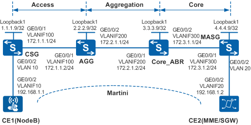
In Figure 1, the access, aggregation, and core layers belong to one AS. To enable the base station NodeB to communicate with the MME/SGW and provide the VLL service, the customer wants to use MPLS at the access layer, so that a complete LSP can be set up over the three layers. To provide an end-to-end service and simplify service configuration and network management, intra-AS seamless MPLS can be configured on the network.

By default, LNP is enabled globally on the device. If a VLANIF interface is used as an AC-side interface for L2VPN, the configuration conflicts with LNP. In this case, run the lnp disable command in the system view to disable LNP.
The lnp disable command has no impact on services before the device restarts. After the device restarts, the device can only forward packets from the VLANs specified by the port default vlan command at Layer 2. The port default vlan 1 command is configured by default, so only packets of VLAN 1 can be forwarded at Layer 2.
Configuration Roadmap
The configuration roadmap is as follows:
Configure IGP protocols at the access, aggregation, and core layers to implement network connectivity at each layer.
Enable MPLS and MPLS LDP on each device and establish an MPLS LSP.
Establish IBGP peer relationships at each layer and enable devices to exchange labeled routes.
Configure the AGG and Core_ABR as RRs to enable the CSG and MASG to obtain loopback routes from each other through route reflection.
Configure a routing policy on each device to control label distribution for a BGP LSP to be established. The ingress node on the BGP LSP needs to distribute an MPLS label to the route advertised to a downstream node. If a transit node on the BGP LSP receives a labeled IPv4 route from its upstream node, the transit node must re-distribute an MPLS label to the labeled IPv4 route before advertising the route to a downstream node.
Enable MPLS L2VPN on the CSG and MASG, and create a Martini connection between them.
Procedure
- On the devices, create a VLAN and a VLANIF interface, assign an IP address to the VLANIF interface, and add a physical interface to the VLAN.
# Configure the CSG. The configurations of CE1, CE2, the AGG, Core_ABR, and MASG are similar to that of the CSG, and are not mentioned here.
<HUAWEI> system-view
[HUAWEI] sysname CSG
[CSG] interface loopback 1
[CSG-LoopBack1] ip address 1.1.1.9 32
[CSG-LoopBack1] quit
[CSG] vlan batch 10 100
[CSG] interface vlanif 100
[CSG-Vlanif100] ip address 172.1.1.1 24
[CSG-Vlanif100] quit
[CSG] interface gigabitethernet 0/0/1
[CSG-GigabitEthernet0/0/1] port link-type trunk
[CSG-GigabitEthernet0/0/1] port trunk allow-pass vlan 100
[CSG-GigabitEthernet0/0/1] quit
[CSG] interface gigabitethernet 0/0/2
[CSG-GigabitEthernet0/0/2] port link-type trunk
[CSG-GigabitEthernet0/0/2] port trunk allow-pass vlan 10
[CSG-GigabitEthernet0/0/2] quit
- Enable OSPF or IS-IS to advertise routes on network segments where each node locates and routes represented by LSR IDs.
# Configure the CSG.
[CSG] ospf 1
[CSG-ospf-1] area 0
[CSG-ospf-1-area-0.0.0.0] network 1.1.1.9 0.0.0.0
[CSG-ospf-1-area-0.0.0.0] network 172.1.1.0 0.0.0.255
[CSG-ospf-1-area-0.0.0.0] quit
[CSG-ospf-1] quit
# Configure the AGG.
[AGG] ospf 1
[AGG-ospf-1] area 0
[AGG-ospf-1-area-0.0.0.0] network 2.2.2.9 0.0.0.0
[AGG-ospf-1-area-0.0.0.0] network 172.1.1.0 0.0.0.255
[AGG-ospf-1-area-0.0.0.0] quit
[AGG-ospf-1] quit
[AGG] isis 1
[AGG-isis-1] network-entity 10.0000.0000.0000.0010.00
[AGG-isis-1] quit
[AGG] interface vlanif 200
[AGG-Vlanif200] isis enable 1
[AGG-Vlanif200] quit
[AGG] interface loopback 1
[AGG-LoopBack1] isis enable 1
[AGG-LoopBack1] quit
# Configure the Core_ABR.
[Core_ABR] ospf 2
[Core_ABR-ospf-2] area 0
[Core_ABR-ospf-2-area-0.0.0.0] network 3.3.3.9 0.0.0.0
[Core_ABR-ospf-2-area-0.0.0.0] network 172.3.1.0 0.0.0.255
[Core_ABR-ospf-2-area-0.0.0.0] quit
[Core_ABR-ospf-2] quit
[Core_ABR] isis 1
[Core_ABR-isis-1] network-entity 10.0000.0000.0000.0020.00
[Core_ABR-isis-1] quit
[Core_ABR] interface vlanif 200
[Core_ABR-Vlanif200] isis enable 1
[Core_ABR-Vlanif200] quit
[Core_ABR] interface loopback 1
[Core_ABR-LoopBack1] isis enable 1
[Core_ABR-LoopBack1] quit
# Configure the MASG.
[MASG] ospf 2
[MASG-ospf-2] area 0
[MASG-ospf-2-area-0.0.0.0] network 4.4.4.9 0.0.0.0
[MASG-ospf-2-area-0.0.0.0] network 172.3.1.0 0.0.0.255
[MASG-ospf-2-area-0.0.0.0] quit
[MASG-ospf-2] quit
- Enable MPLS and MPLS LDP globally on each device.
# Configure the CSG. The configurations of the AGG, Core_ABR, and MASG are similar to that of the CSG, and are not mentioned here.
[CSG] mpls lsr-id 1.1.1.9
[CSG] mpls
[CSG-mpls] quit
[CSG] mpls ldp
[CSG-mpls-ldp] quit
[CSG] interface vlanif 100
[CSG-Vlanif100] mpls
[CSG-Vlanif100] mpls ldp
[CSG-Vlanif100] quit
- Establish IBGP peer relationships at each layer and enable devices to exchange labeled routes.
# Configure the CSG.
[CSG] bgp 100
[CSG-bgp] peer 2.2.2.9 as-number 100
[CSG-bgp] peer 2.2.2.9 connect-interface LoopBack 1
[CSG-bgp] peer 2.2.2.9 label-route-capability
[CSG-bgp] network 1.1.1.9 32
[CSG-bgp] quit
# Configure the AGG.
[AGG] bgp 100
[AGG-bgp] peer 1.1.1.9 as-number 100
[AGG-bgp] peer 1.1.1.9 connect-interface LoopBack 1
[AGG-bgp] peer 1.1.1.9 label-route-capability
[AGG-bgp] peer 3.3.3.9 as-number 100
[AGG-bgp] peer 3.3.3.9 connect-interface LoopBack 1
[AGG-bgp] peer 3.3.3.9 label-route-capability
[AGG-bgp] quit
# Configure the Core_ABR.
[Core_ABR] bgp 100
[Core_ABR-bgp] peer 2.2.2.9 as-number 100
[Core_ABR-bgp] peer 2.2.2.9 connect-interface LoopBack 1
[Core_ABR-bgp] peer 2.2.2.9 label-route-capability
[Core_ABR-bgp] peer 4.4.4.9 as-number 100
[Core_ABR-bgp] peer 4.4.4.9 connect-interface LoopBack 1
[Core_ABR-bgp] peer 4.4.4.9 label-route-capability
[Core_ABR-bgp] quit
# Configure the MASG.
[MASG] bgp 100
[MASG-bgp] peer 3.3.3.9 as-number 100
[MASG-bgp] peer 3.3.3.9 connect-interface LoopBack 1
[MASG-bgp] peer 3.3.3.9 label-route-capability
[MASG-bgp] network 4.4.4.9 32
[MASG-bgp] quit
- Configure the AGG and Core_ABR as RRs to enable the CSG and MASG to obtain loopback routes from each other through route reflection.
# Configure the AGG.
[AGG] bgp 100
[AGG-bgp] peer 1.1.1.9 reflect-client
[AGG-bgp] peer 1.1.1.9 next-hop-local
[AGG-bgp] peer 3.3.3.9 reflect-client
[AGG-bgp] peer 3.3.3.9 next-hop-local
[AGG-bgp] quit
# Configure the Core_ABR.
[Core_ABR] bgp 100
[Core_ABR-bgp] peer 2.2.2.9 reflect-client
[Core_ABR-bgp] peer 2.2.2.9 next-hop-local
[Core_ABR-bgp] peer 4.4.4.9 reflect-client
[Core_ABR-bgp] peer 4.4.4.9 next-hop-local
[Core_ABR-bgp] quit
- Configure a routing policy on each device to establish BGP LSPs.
# Create a routing policy on the CSG and apply the routing policy to its peer. The configuration of the MASG is similar to that of the CSG, and is not mentioned here.
[CSG] route-policy policy1 permit node 1
[CSG-route-policy] apply mpls-label
[CSG-route-policy] quit
[CSG] bgp 100
[CSG-bgp] peer 2.2.2.9 route-policy policy1 export
[CSG-bgp] quit
# Create a routing policy on the AGG and apply the routing policy to its peer. The configuration of the Core_ABR is similar to that of the AGG, and is not mentioned here.
[AGG] route-policy policy1 permit node 1
[AGG-route-policy] if-match mpls-label
[AGG-route-policy] apply mpls-label
[AGG-route-policy] quit
[AGG] bgp 100
[AGG-bgp] peer 1.1.1.9 route-policy policy1 export
[AGG-bgp] peer 3.3.3.9 route-policy policy1 export
[AGG-bgp] quit
After the configuration is complete, run the display ip routing-table command on the CSG or MASG. You can view routes to the loopback address of each other.
The display on the CSG is used as an example.
[CSG] display ip routing-table
Route Flags: R - relay, D - download to fib, T - to vpn-instance
------------------------------------------------------------------------------
Routing Tables: Public
         Destinations : 7        Routes : 7

Destination/Mask    Proto   Pre  Cost      Flags NextHop         Interface

        1.1.1.9/32  Direct  0    0           D   127.0.0.1       LoopBack1
        2.2.2.9/32  OSPF    10   1           D   172.1.1.2       Vlanif100
        4.4.4.9/32  IBGP    255  0          RD   2.2.2.9         Vlanif100
      127.0.0.0/8   Direct  0    0           D   127.0.0.1       InLoopBack0
      127.0.0.1/32  Direct  0    0           D   127.0.0.1       InLoopBack0
      172.1.1.0/24  Direct  0    0           D   172.1.1.1       Vlanif100
      172.1.1.1/32  Direct  0    0           D   127.0.0.1       Vlanif100
Run the display mpls lsp command on the CSG or MASG to check the LSP configuration.
The display on the CSG is used as an example.
[CSG] display mpls lsp ------------------------------------------------------------------------------- LSP Information: BGP LSP ------------------------------------------------------------------------------- FEC In/Out Label In/Out IF Vrf Name 1.1.1.9/32 4099/NULL -/- 4.4.4.9/32 NULL/4106 -/- Flag after Out IF: (I) - LSP Is Only Iterated by RLFA ------------------------------------------------------------------------------- LSP Information: LDP LSP ------------------------------------------------------------------------------- FEC In/Out Label In/Out IF Vrf Name 1.1.1.9/32 3/NULL -/- 2.2.2.9/32 NULL/3 -/Vlanif100 2.2.2.9/32 4097/3 -/Vlanif100 - Enable MPLS L2VPN on the CSG and MASG, and create a Martini connection between them.
# Enable MPLS L2VPN on the CSG and establish a remote LDP session. The configuration of the MASG is similar to that of the CSG, and is not mentioned here.
[CSG] mpls l2vpn
[CSG-l2vpn] quit
[CSG] mpls ldp remote-peer 4.4.4.9
[CSG-mpls-ldp-remote-4.4.4.9] remote-ip 4.4.4.9
[CSG-mpls-ldp-remote-4.4.4.9] quit
# Establish a Martini connection from the CSG to the MASG. The configuration of the MASG is similar to that of the CSG, and is not mentioned here.
[CSG] lnp disable [CSG] interface vlanif 10 [CSG-Vlanif10] mpls l2vc 4.4.4.9 100 [CSG-Vlanif10] quit - Verify the configuration.
Check the L2VPN connection on the CSG or MASG. You can see that an L2 VC connection is set up and is in the Up state.
The display on the CSG is used as an example.[CSG] display mpls l2vc interface vlanif 10 *client interface : Vlanif10 is up Administrator PW : no session state : up AC status : up Ignore AC state : disable VC state : up Label state : 0 Token state : 0 VC ID : 100 VC type : VLAN destination : 4.4.4.9 local group ID : 0 remote group ID : 0 local VC label : 23552 remote VC label : 23552 local AC OAM State : up local PSN OAM State : up local forwarding state : forwarding local status code : 0x0 remote AC OAM state : up remote PSN OAM state : up remote forwarding state: forwarding remote status code : 0x0 ignore standby state : no BFD for PW : unavailable VCCV State : up manual fault : not set active state : active forwarding entry : exist link state : up local VC MTU : 1500 remote VC MTU : 1500 local VCCV : alert ttl lsp-ping bfd remote VCCV : alert ttl lsp-ping bfd local control word : disable remote control word : disable tunnel policy name : -- PW template name : -- primary or secondary : primary load balance type : flow Access-port : false Switchover Flag : false VC tunnel/token info : 1 tunnels/tokens NO.0 TNL type : lsp , TNL ID : 0x10031 Backup TNL type : lsp , TNL ID : 0x0 create time : 1 days, 22 hours, 15 minutes, 9 seconds up time : 0 days, 22 hours, 54 minutes, 57 seconds last change time : 0 days, 22 hours, 54 minutes, 57 seconds VC last up time : 2013/09/05 19:26:37 VC total up time : 1 days, 20 hours, 42 minutes, 30 seconds CKey : 8 NKey : 3 PW redundancy mode : -- AdminPw interface : -- AdminPw link state : -- Diffserv Mode : uniform Service Class : -- Color : -- DomainId : -- Domain Name : --CE1 and CE2 can ping each other.
The display on CE1 is used as an example.
[CE1] ping 192.168.1.2
  PING 192.168.1.2: 56  data bytes, press CTRL_C to break
    Reply from 192.168.1.2: bytes=56 Sequence=1 ttl=255 time=31 ms
    Reply from 192.168.1.2: bytes=56 Sequence=2 ttl=255 time=10 ms
    Reply from 192.168.1.2: bytes=56 Sequence=3 ttl=255 time=5 ms
    Reply from 192.168.1.2: bytes=56 Sequence=4 ttl=255 time=2 ms
    Reply from 192.168.1.2: bytes=56 Sequence=5 ttl=255 time=28 ms
  --- 192.168.1.2 ping statistics ---
    5 packet(s) transmitted
    5 packet(s) received
    0.00% packet loss
    round-trip min/avg/max = 2/15/31 ms
Configuration Files
CE1 configuration file
#
sysname CE1
#
vlan batch 10
#
interface Vlanif10
 ip address 192.168.1.1 255.255.255.0
#
interface GigabitEthernet0/0/2
 port link-type trunk
 port trunk allow-pass vlan 10
#
return
CE2 configuration file
#
sysname CE2
#
vlan batch 20
#
interface Vlanif20
 ip address 192.168.1.2 255.255.255.0
#
interface GigabitEthernet0/0/2
 port link-type trunk
 port trunk allow-pass vlan 20
#
return
CSG configuration file
#
sysname CSG
#
vlan batch 10 100
#
lnp disable
#
mpls lsr-id 1.1.1.9
mpls
#
mpls l2vpn
#
mpls ldp
#
#
mpls ldp remote-peer 4.4.4.9
 remote-ip 4.4.4.9
#
interface Vlanif10
 mpls l2vc 4.4.4.9 100
#
interface Vlanif 100
 ip address 172.1.1.1 255.255.255.0
 mpls
 mpls ldp
#
interface GigabitEthernet0/0/1
 port link-type trunk
 port trunk allow-pass vlan 100
#
interface GigabitEthernet0/0/2
 port link-type trunk
 port trunk allow-pass vlan 10
#
interface LoopBack1
 ip address 1.1.1.9 255.255.255.255
#
bgp 100
 peer 2.2.2.9 as-number 100
 peer 2.2.2.9 connect-interface LoopBack1
 #
 ipv4-family unicast
  undo synchronization
  network 1.1.1.9 255.255.255.255
  peer 2.2.2.9 enable
  peer 2.2.2.9 route-policy policy1 export
  peer 2.2.2.9 label-route-capability
#
ospf 1
 area 0.0.0.0
  network 1.1.1.9 0.0.0.0
  network 172.1.1.0 0.0.0.255
#
route-policy policy1 permit node 1
 apply mpls-label
#
return
AGG configuration file
#
sysname AGG
#
vlan batch 100 200
#
mpls lsr-id 2.2.2.9
mpls
#
mpls ldp
#
isis 1
 network-entity 10.0000.0000.0000.0010.00
#
interface Vlanif100
 ip address 172.1.1.2 255.255.255.0
 mpls
 mpls ldp
#
interface Vlanif200
 ip address 172.2.1.1 255.255.255.0
 isis enable 1
 mpls
 mpls ldp
#
interface GigabitEthernet0/0/1
 port link-type trunk
 port trunk allow-pass vlan 100
#
interface GigabitEthernet0/0/2
 port link-type trunk
 port trunk allow-pass vlan 200
#
interface LoopBack1
 ip address 2.2.2.9 255.255.255.255
 isis enable 1
#
bgp 100
 peer 1.1.1.9 as-number 100
 peer 1.1.1.9 connect-interface LoopBack1
 peer 3.3.3.9 as-number 100
 peer 3.3.3.9 connect-interface LoopBack1
 #
 ipv4-family unicast
  undo synchronization
  peer 1.1.1.9 enable
  peer 1.1.1.9 route-policy policy1 export
  peer 1.1.1.9 reflect-client
  peer 1.1.1.9 next-hop-local
  peer 1.1.1.9 label-route-capability
  peer 3.3.3.9 enable
  peer 3.3.3.9 route-policy policy1 export
  peer 3.3.3.9 reflect-client
  peer 3.3.3.9 next-hop-local
  peer 3.3.3.9 label-route-capability
#
ospf 1
 area 0.0.0.0
  network 2.2.2.9 0.0.0.0
  network 172.1.1.0 0.0.0.255
#
route-policy policy1 permit node 1
 if-match mpls-label
 apply mpls-label
#
return
Core_ABR configuration file
#
sysname Core_ABR
#
vlan batch 200 300
#
mpls lsr-id 3.3.3.9
mpls
#
mpls ldp
#
isis 1
 network-entity 10.0000.0000.0000.0020.00
#
interface Vlanif200
 ip address 172.2.1.2 255.255.255.0
 isis enable 1
 mpls
 mpls ldp
#
interface Vlanif300
 ip address 172.3.1.1 255.255.255.0
 mpls
 mpls ldp
#
interface GigabitEthernet0/0/1
 port link-type trunk
 port trunk allow-pass vlan 200
#
interface GigabitEthernet0/0/2
 port link-type trunk
 port trunk allow-pass vlan 300
#
interface LoopBack1
 ip address 3.3.3.9 255.255.255.255
 isis enable 1
#
bgp 100
 peer 2.2.2.9 as-number 100
 peer 2.2.2.9 connect-interface LoopBack1
 peer 4.4.4.9 as-number 100
 peer 4.4.4.9 connect-interface LoopBack1
 #
 ipv4-family unicast
  undo synchronization
  peer 2.2.2.9 enable
  peer 2.2.2.9 route-policy policy1 export
  peer 2.2.2.9 reflect-client
  peer 2.2.2.9 next-hop-local
  peer 2.2.2.9 label-route-capability
  peer 4.4.4.9 enable
  peer 4.4.4.9 route-policy policy1 export
  peer 4.4.4.9 reflect-client
  peer 4.4.4.9 next-hop-local
  peer 4.4.4.9 label-route-capability
#
ospf 2
 area 0.0.0.0
  network 3.3.3.9 0.0.0.0
  network 172.3.1.0 0.0.0.255
#
route-policy policy1 permit node 1
 if-match mpls-label
 apply mpls-label
#
return
MASG configurations file
#
sysname MASG
#
vlan batch 20 300
#
mpls lsr-id 4.4.4.9
mpls
#
mpls l2vpn
#
mpls ldp
#
#
mpls ldp remote-peer 1.1.1.9
 remote-ip 1.1.1.9
#
interface Vlanif20
 mpls l2vc 1.1.1.9 100
#
interface Vlanif300
 ip address 172.3.1.2 255.255.255.0
 mpls
 mpls ldp
#
interface GigabitEthernet0/0/1
 port link-type trunk
 port trunk allow-pass vlan 300
#
interface GigabitEthernet0/0/2
 port link-type trunk
 port trunk allow-pass vlan 20
#
interface LoopBack1
 ip address 4.4.4.9 255.255.255.255
#
bgp 100
 peer 3.3.3.9 as-number 100
 peer 3.3.3.9 connect-interface LoopBack1
 #
 ipv4-family unicast
  undo synchronization
  network 4.4.4.9 255.255.255.255
  peer 3.3.3.9 enable
  peer 3.3.3.9 route-policy policy1 export
  peer 3.3.3.9 label-route-capability
#
ospf 2
 area 0.0.0.0
  network 4.4.4.9 0.0.0.0
  network 172.3.1.0 0.0.0.255
#
route-policy policy1 permit node 1
 apply mpls-label
#
return