Example for Configuring SEP on a Closed Ring Network
Networking Requirements
Generally, redundant links are used to connect an Ethernet switching network to an upper-layer network to provide link backup and enhance network reliability. The use of redundant links, however, may produce loops, causing broadcast storms and rendering the MAC address table unstable. As a result, communication quality deteriorates, and services may even be interrupted. SEP can be deployed on the ring network to eliminate loops and restore communication if a link fault occurs.
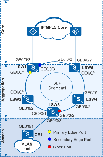
In the closed ring networking, CE1 is dual-homed to a Layer 2 network through multiple Layer 2 switching devices. The two edge devices connected to the upper-layer Layer 2 network are directly connected to each other. The closed ring network is deployed at the aggregation layer to transparently transmit Layer 2 unicast and multicast packets. SEP runs at the aggregation layer to implement link redundancy.In Figure 1, Layer 2 switching devices LSW1 to LSW5 form a ring network.
When there is no faulty link on a ring network, SEP can eliminate loops on the network.
When a link fails on the ring network, SEP can rapidly restore communication between nodes on the network.
Configuration Roadmap
The configuration roadmap is as follows:
Configure basic SEP functions.
- Configure SEP segment 1 on LSW1 to LSW5 and configure VLAN 10 as the control VLAN of SEP segment 1.
Add all devices on the ring to SEP segment 1, and configure the roles of GE0/0/1 and GE0/0/3 of LSW1 in SEP segment 1.
On the device where the primary edge interface is located, specify the interface with the highest priority to block.
Set priorities of the interfaces in the SEP segment.
Set the highest priority for GE0/0/2 of LSW3 and retain the default priority of the other interfaces so that GE0/0/2 of LSW3 will be blocked.
Configure delayed preemption on the device where the primary edge interface is located.
Configure the Layer 2 forwarding function on CE1 and LSW1 to LSW5.
Procedure
- Configure basic SEP functions.
Configure SEP segment 1 on LSW1 to LSW5 and configure VLAN 10 as the control VLAN of SEP segment 1.
# Configure LSW1.<HUAWEI> system-view [HUAWEI] sysname LSW1 [LSW1] sep segment 1 [LSW1-sep-segment1] control-vlan 10 [LSW1-sep-segment1] protected-instance all [LSW1-sep-segment1] quit
# Configure LSW2.<HUAWEI> system-view [HUAWEI] sysname LSW2 [LSW2] sep segment 1 [LSW2-sep-segment1] control-vlan 10 [LSW2-sep-segment1] protected-instance all [LSW2-sep-segment1] quit
# Configure LSW3.<HUAWEI> system-view [HUAWEI] sysname LSW3 [LSW3] sep segment 1 [LSW3-sep-segment1] control-vlan 10 [LSW3-sep-segment1] protected-instance all [LSW3-sep-segment1] quit
# Configure LSW4.<HUAWEI> system-view [HUAWEI] sysname LSW4 [LSW4] sep segment 1 [LSW4-sep-segment1] control-vlan 10 [LSW4-sep-segment1] protected-instance all [LSW4-sep-segment1] quit
# Configure LSW5.<HUAWEI> system-view [HUAWEI] sysname LSW5 [LSW5] sep segment 1 [LSW5-sep-segment1] control-vlan 10 [LSW5-sep-segment1] protected-instance all [LSW5-sep-segment1] quit

The control VLAN must be a VLAN that has not been created or used, but the configuration file automatically displays the command for creating the VLAN.
Each SEP segment must be configured with a control VLAN. After an interface is added to a SEP segment configured with a control VLAN, the interface will be automatically added to the control VLAN.
Add all devices on the ring to SEP segment 1 and configure interface roles on the devices.
By default, STP is enabled on a Layer 2 interface. Before adding an interface to a SEP segment, disable STP on the interface.
# On LSW1, configure GE0/0/1 as the primary edge interface and GE0/0/3 as the secondary edge interface.
[LSW1] interface gigabitethernet 0/0/1
[LSW1-GigabitEthernet0/0/1] port link-type hybrid
[LSW1-GigabitEthernet0/0/1] stp disable
[LSW1-GigabitEthernet0/0/1] sep segment 1 edge primary
[LSW1-GigabitEthernet0/0/1] quit
[LSW1] interface gigabitethernet 0/0/3
[LSW1-GigabitEthernet0/0/3] port link-type hybrid
[LSW1-GigabitEthernet0/0/3] stp disable
[LSW1-GigabitEthernet0/0/3] sep segment 1 edge secondary
[LSW1-GigabitEthernet0/0/3] quit
# Configure LSW2.[LSW2] interface gigabitethernet 0/0/1 [LSW2-GigabitEthernet0/0/1] port link-type hybrid [LSW2-GigabitEthernet0/0/1] stp disable [LSW2-GigabitEthernet0/0/1] sep segment 1 [LSW2-GigabitEthernet0/0/1] quit [LSW2] interface gigabitethernet 0/0/2 [LSW2-GigabitEthernet0/0/2] port link-type hybrid [LSW2-GigabitEthernet0/0/2] stp disable [LSW2-GigabitEthernet0/0/2] sep segment 1 [LSW2-GigabitEthernet0/0/2] quit
# Configure LSW3.[LSW3] interface gigabitethernet 0/0/1 [LSW3-GigabitEthernet0/0/1] port link-type hybrid [LSW3-GigabitEthernet0/0/1] stp disable [LSW3-GigabitEthernet0/0/1] sep segment 1 [LSW3-GigabitEthernet0/0/1] quit [LSW3] interface gigabitethernet 0/0/2 [LSW3-GigabitEthernet0/0/2] port link-type hybrid [LSW3-GigabitEthernet0/0/2] stp disable [LSW3-GigabitEthernet0/0/2] sep segment 1 [LSW3-GigabitEthernet0/0/2] quit
# Configure LSW4.[LSW4] interface gigabitethernet 0/0/1 [LSW4-GigabitEthernet0/0/1] port link-type hybrid [LSW4-GigabitEthernet0/0/1] stp disable [LSW4-GigabitEthernet0/0/1] sep segment 1 [LSW4-GigabitEthernet0/0/1] quit [LSW4] interface gigabitethernet 0/0/2 [LSW4-GigabitEthernet0/0/2] port link-type hybrid [LSW4-GigabitEthernet0/0/2] stp disable [LSW4-GigabitEthernet0/0/2] sep segment 1 [LSW4-GigabitEthernet0/0/2] quit
# Configure LSW5.
[LSW5] interface gigabitethernet 0/0/1
[LSW5-GigabitEthernet0/0/1] port link-type hybrid
[LSW5-GigabitEthernet0/0/1] stp disable
[LSW5-GigabitEthernet0/0/1] sep segment 1
[LSW5-GigabitEthernet0/0/1] quit
[LSW5] interface gigabitethernet 0/0/3
[LSW5-GigabitEthernet0/0/3] port link-type hybrid
[LSW5-GigabitEthernet0/0/3] stp disable
[LSW5-GigabitEthernet0/0/3] sep segment 1
[LSW5-GigabitEthernet0/0/3] quit
Specify an interface to block.
# On LSW1 where the primary edge interface is located, specify the interface with the highest priority to block.
[LSW1] sep segment 1
[LSW1-sep-segment1] block port optimal
Set the priority of GE0/0/2 on LSW3.
[LSW3] interface gigabitethernet 0/0/2
[LSW3-GigabitEthernet0/0/2] sep segment 1 priority 128
[LSW3-GigabitEthernet0/0/2] quit
Configure the preemption mode.
# Configure delayed preemption on LSW1.
[LSW1-sep-segment1] preempt delay 30
[LSW1-sep-segment1] quit
You must set the preemption delay when delayed preemption is used because there is no default delay time.
When the last faulty interface recovers, edge interfaces do not receive any fault notification packet. If the primary edge interface does not receive any fault notification packet, it starts the delay timer. After the delay timer expires, nodes in the SEP segment start blocked interface preemption.
To implement delayed preemption in this example, simulate a port fault and then rectify the fault. For example:
Run the shutdown command on GE0/0/2 of LSW2 to simulate an interface fault, and then run the undo shutdown command on GE0/0/2 to rectify the fault.
- Configure the Layer 2 forwarding function on CE1 and LSW1 to LSW5.
For details about the configuration, see the configuration files.
- Verify the configuration.
Run the shutdown command on GE0/0/1 of LSW3 to simulate an interface fault, and then run the display sep interface command on LSW3 to check whether GE0/0/2 of LSW3 has switched from the Discarding state to the Forwarding state.
<LSW3> display sep interface gigabitethernet 0/0/2
SEP segment 1
----------------------------------------------------------------
Interface           Port Role     Neighbor Status     Port Status
----------------------------------------------------------------
GE0/0/2             common        up                  forwarding
Configuration Files
LSW1 configuration file
#
 sysname LSW1
#
 vlan batch 10 100 200
#
sep segment 1
 control-vlan 10
 block port optimal
 preempt delay 30
 protected-instance 0 to 48
#
interface GigabitEthernet0/0/1
 port link-type hybrid
 port hybrid tagged vlan 10 100
 stp disable
 sep segment 1 edge primary
#
interface GigabitEthernet0/0/2
 port link-type hybrid
 port hybrid pvid vlan 200
 port hybrid tagged vlan 100
 port hybrid untagged vlan 200
#
interface GigabitEthernet0/0/3
 port link-type hybrid
 port hybrid tagged vlan 10 100 200
 stp disable
 sep segment 1 edge secondary
#
return
LSW2 configuration file
#
 sysname LSW2
#
 vlan batch 10 100
#
sep segment 1
 control-vlan 10
 protected-instance 0 to 48
#
interface GigabitEthernet0/0/1
 port link-type hybrid
 port hybrid tagged vlan 10 100
 stp disable
 sep segment 1
#
interface GigabitEthernet0/0/2
 port link-type hybrid
 port hybrid tagged vlan 10 100
 stp disable
 sep segment 1
#
return
LSW3 configuration file
#
 sysname LSW3
#
 vlan batch 10 100
#
sep segment 1
 control-vlan 10
 protected-instance 0 to 48
#
interface GigabitEthernet0/0/1
 port link-type hybrid
 port hybrid tagged vlan 10 100
 stp disable
 sep segment 1
#
interface GigabitEthernet0/0/2
 port link-type hybrid
 port hybrid tagged vlan 10 100
 stp disable
 sep segment 1
 sep segment 1 priority 128
#
interface GigabitEthernet0/0/3
 port link-type hybrid
 port hybrid tagged vlan 100
#
return
LSW4 configuration file
#
 sysname LSW4
#
 vlan batch 10 100
#
sep segment 1
 control-vlan 10
 protected-instance 0 to 48
#
interface GigabitEthernet0/0/1
 port link-type hybrid
 port hybrid tagged vlan 10 100
 stp disable
 sep segment 1
#
interface GigabitEthernet0/0/2
 port link-type hybrid
 port hybrid tagged vlan 10 100
 stp disable
 sep segment 1
#
return
LSW5 configuration file
#
 sysname LSW5
#
 vlan batch 10 100 200
#
sep segment 1
 control-vlan 10
 protected-instance 0 to 48
#
interface GigabitEthernet0/0/1
 port link-type hybrid
 port hybrid tagged vlan 10 100
 stp disable
 sep segment 1
#
interface GigabitEthernet0/0/2
 port link-type hybrid
 port hybrid pvid vlan 200
 port hybrid tagged vlan 100
 port hybrid untagged vlan 200
#
interface GigabitEthernet0/0/3
 port link-type hybrid
 port hybrid tagged vlan 10 100 200
 stp disable
 sep segment 1
#
return
CE1 configuration file
#
 sysname CE1
#
 vlan batch 100
#
interface GigabitEthernet0/0/1
 port link-type hybrid
 port hybrid tagged vlan 100
#
return