Example for Configuring SEP Multi-Instance
Networking Requirements
On a closed ring network, two SEP segments are configured to process different VLAN services, implement load balancing, and provide link backup.
In typical SEP networking, a physical ring can be configured with only one SEP segment in which only one interface can be blocked. If an interface in a complete SEP segment is blocked, all service data is transmitted only along the path where the primary edge interface is located. The path where the secondary edge interface is located remains idle, wasting bandwidth.
To improve bandwidth efficiency and implement traffic load balancing, Huawei develops SEP multi-instance.
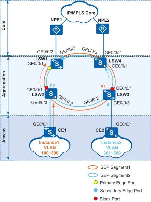
In Figure 1, a ring network comprising Layer 2 switches (LSW1 to LSW5) is connected to the network. SEP runs at the aggregation layer. SEP multi-instance is configured on LSW1 to LSW4 to allow for two SEP segments to improve bandwidth efficiency, implement load balancing, and provide link backup.
Configuration Roadmap
The configuration roadmap is as follows:
Configure basic SEP functions.
Create two SEP segments and a control VLAN on LSW1 to LSW4.
Different SEP segments can use the same control VLAN.
- Configure SEP protected instances, and set mappings between SEP protected instances and user VLANs to ensure that topology changes affect only corresponding VLANs.
Add all the devices on the ring network to the SEP segments, and configure GE0/0/1 as the primary edge interface and GE0/0/3 as the secondary edge interface on LSW1.
- Configure an interface blocking mode on the device where the primary edge interface resides.
- Configure the preemption mode to ensure that the specified interface is blocked when a fault is rectified.
Configure the Layer 2 forwarding function on CE1, CE2, and LSW1 to LSW4.
Procedure
- Configure basic SEP functions.
Configure SEP segment 1 and control VLAN 10.
# Configure LSW1.<HUAWEI> system-view[HUAWEI] sysname LSW1
[LSW1] sep segment 1[LSW1-sep-segment1] control-vlan 10[LSW1-sep-segment1] quit# Configure LSW2.<HUAWEI> system-view[HUAWEI] sysname LSW2
[LSW2] sep segment1[LSW2-sep-segment1] control-vlan 10[LSW2-sep-segment1] quit# Configure LSW3.<HUAWEI> system-view[HUAWEI] sysname LSW3
[LSW3] sep segment 1[LSW3-sep-segment1] control-vlan 10[LSW3-sep-segment1] quit# Configure LSW4.<HUAWEI> system-view[HUAWEI] sysname LSW4
[LSW4] sep segment 1[LSW4-sep-segment1] control-vlan 10[LSW4-sep-segment1] quitConfigure SEP segment 2 and control VLAN 10.
# Configure LSW1.[LSW1] sep segment 2[LSW1-sep-segment2] control-vlan 10[LSW1-sep-segment2] quit# Configure LSW2.[LSW2] sep segment2[LSW2-sep-segment2] control-vlan 10[LSW2-sep-segment2] quit# Configure LSW3.[LSW3] sep segment 2[LSW3-sep-segment2] control-vlan 10[LSW3-sep-segment2] quit# Configure LSW4.[LSW4] sep segment 2[LSW4-sep-segment2] control-vlan 10[LSW4-sep-segment2] quit

- The control VLAN must be a new one.
- The command used to create a common VLAN is automatically displayed in a configuration file.
- Each SEP segment must be configured with a control VLAN. After being added to a SEP segment configured with a control VLAN, an interface is added to the control VLAN automatically. You do not need to run the port trunk allow-pass vlan command. In the configuration file, the port trunk allow-pass vlan command, however, is displayed in the view of the interface added to the SEP segment.
- Configure SEP protected instances, and configure mappings
between SEP protected instances and user VLANs.
# Configure LSW1.
[LSW1] vlan batch 100 to 500[LSW1] sep segment 1[LSW1-sep-segment1] protected-instance 1[LSW1-sep-segment1] quit[LSW1] sep segment 2[LSW1-sep-segment2] protected-instance 2[LSW1-sep-segment2] quit[LSW1] stp region-configuration[LSW1-mst-region] instance 1 vlan 100 to 300[LSW1-mst-region] instance 2 vlan 301 to 500[LSW1-mst-region] active region-configuration[LSW1-mst-region] quitThe configurations of LSW2 to LSW4 are similar to that of LSW1, and are not mentioned here. For details, see the configuration files.
- Add all the devices on the ring network to the SEP segments
and configure interface roles.
By default, STP is enabled on a Layer 2 interface. Before adding an interface to a SEP segment, disable STP on the interface.
# On LSW1, configure GE0/0/1 as the primary edge interface and GE0/0/3 as the secondary edge interface.
[LSW1] interface gigabitethernet 0/0/1
[LSW1-GigabitEthernet0/0/1] port link-type hybrid
[LSW1-GigabitEthernet0/0/1] stp disable
[LSW1-GigabitEthernet0/0/1] sep segment 1 edge primary
[LSW1-GigabitEthernet0/0/1] sep segment 2 edge primary
[LSW1-GigabitEthernet0/0/1] quit
[LSW1] interface gigabitethernet 0/0/3
[LSW1-GigabitEthernet0/0/3] port link-type hybrid
[LSW1-GigabitEthernet0/0/3] stp disable
[LSW1-GigabitEthernet0/0/3] sep segment 1 edge secondary
[LSW1-GigabitEthernet0/0/3] sep segment 2 edge secondary
[LSW1-GigabitEthernet0/0/3] quit
# Configure LSW2.[LSW2] interface gigabitethernet 0/0/1
[LSW2-GigabitEthernet0/0/1] port link-type hybrid
[LSW2-GigabitEthernet0/0/1] stp disable
[LSW2-GigabitEthernet0/0/1] sep segment 1
[LSW2-GigabitEthernet0/0/1] sep segment 2
[LSW2-GigabitEthernet0/0/1] quit
[LSW2] interface gigabitethernet 0/0/2
[LSW2-GigabitEthernet0/0/2] port link-type hybrid
[LSW2-GigabitEthernet0/0/2] stp disable
[LSW2-GigabitEthernet0/0/2] sep segment 1
[LSW2-GigabitEthernet0/0/2] sep segment 2
[LSW2-GigabitEthernet0/0/2] quit
# Configure LSW3.[LSW3] interface gigabitethernet 0/0/1
[LSW3-GigabitEthernet0/0/1] port link-type hybrid
[LSW3-GigabitEthernet0/0/1] stp disable
[LSW3-GigabitEthernet0/0/1] sep segment 1
[LSW3-GigabitEthernet0/0/1] sep segment 2
[LSW3-GigabitEthernet0/0/1] quit
[LSW3] interface gigabitethernet 0/0/2
[LSW3-GigabitEthernet0/0/2] port link-type hybrid
[LSW3-GigabitEthernet0/0/2] stp disable
[LSW3-GigabitEthernet0/0/2] sep segment 1
[LSW3-GigabitEthernet0/0/2] sep segment 2
[LSW3-GigabitEthernet0/0/2] quit
# Configure LSW4.
[LSW4] interface gigabitethernet 0/0/1
[LSW4-GigabitEthernet0/0/1] port link-type hybrid
[LSW4-GigabitEthernet0/0/1] stp disable
[LSW4-GigabitEthernet0/0/1] sep segment 1
[LSW4-GigabitEthernet0/0/1] sep segment 2
[LSW4-GigabitEthernet0/0/1] quit
[LSW4] interface gigabitethernet 0/0/3
[LSW4-GigabitEthernet0/0/3] port link-type hybrid
[LSW4-GigabitEthernet0/0/3] stp disable
[LSW4-GigabitEthernet0/0/3] sep segment 1
[LSW4-GigabitEthernet0/0/3] sep segment 2
[LSW4-GigabitEthernet0/0/3] quit
- Specify an interface to block.
# Configure delayed preemption and block an interface based on the device and interface names on LSW1 where the primary edge interface is located.
[LSW1] sep segment 1[LSW1-sep-segment1] block port sysname LSW3 interface gigabitethernet 0/0/1
[LSW1-sep-segment1] preempt delay 15[LSW1-sep-segment1] quit[LSW1] sep segment 2[LSW1-sep-segment2] block port sysname LSW2 interface gigabitethernet 0/0/1
[LSW1-sep-segment2] preempt delay 15[LSW1-sep-segment2] quit - In this configuration example, an interface fault needs to be simulated and then rectified to implement delayed preemption. To ensure that delayed preemption takes effect on the two SEP segments, simulate an interface fault in the two SEP segments. For example:
- In SEP segment 1, run the shutdown command on GE 0/0/1 of LSW2 to simulate an interface fault. Then, run the undo shutdown command on GE0/0/1 to simulate interface fault recovery.
- In SEP segment 2, run the shutdown command on GE 0/0/1 of LSW3 to simulate an interface fault. Then, run the undo shutdown command on GE0/0/1 to simulate interface fault recovery.
- Configure the Layer 2 forwarding function on CE1, CE2,
and LSW1 to LSW4.
The configuration details are not mentioned here. For details, see the configuration files.
- Verify the configuration.
Simulate a fault, and then check whether the status of the blocked interface changes from blocked to forwarding.
Run the shutdown command on GE0/0/1 of LSW2 to simulate an interface fault.
Run the display sep interface command on LSW3 to check whether the status of GE0/0/1 in SEP segment 1 changes from blocked to forwarding.
[LSW3] display sep interface gigabitethernet 0/0/1
SEP segment 1
----------------------------------------------------------------
Interface           Port Role     Neighbor Status     Port Status
----------------------------------------------------------------
GE0/0/1             common        up                  forwarding
SEP segment 2
----------------------------------------------------------------
Interface           Port Role     Neighbor Status     Port Status
----------------------------------------------------------------
GE0/0/1             common        up                  forwarding
The preceding command output shows that the status of GE0/0/1 changes from blocked to forwarding and the forwarding path change in SEP segment 1 does not affect the forwarding path in SEP segment 2.
Configuration Files
LSW1 configuration file
#
sysname LSW1
#
vlan batch 10 100 to 500
#
stp region-configuration
  instance 1 vlan 100 to 300
  instance 2 vlan 301 to 500
  active region-configuration
#
sep segment 1
 control-vlan 10
 block port sysname LSW3 interface GigabitEthernet0/0/1
 preempt delay 15
 protected-instance 1
sep segment 2
 control-vlan 10
 block port sysname LSW2 interface GigabitEthernet0/0/1
 preempt delay 15
 protected-instance 2
#
interface GigabitEthernet0/0/1
 port link-type hybrid
 port hybrid tagged vlan 10 100 to 500
 stp disable
 sep segment 1 edge primary
 sep segment 2 edge primary
#
interface GigabitEthernet0/0/3
 port link-type hybrid
 port hybrid tagged vlan 10 100 to 500
 stp disable
 sep segment 1 edge secondary
 sep segment 2 edge secondary
#
return
LSW2 configuration file
#
sysname LSW2
#
vlan batch 10 100 to 500
#
stp region-configuration
  instance 1 vlan 100 to 300
  instance 2 vlan 301 to 500
  active region-configuration
#
sep segment 1
 control-vlan 10
 protected-instance 1
sep segment 2
 control-vlan 10
 protected-instance 2
#
interface GigabitEthernet0/0/1
 port link-type hybrid
 port hybrid tagged vlan 10 100 to 500
 stp disable
 sep segment 1
 sep segment 2
#
interface GigabitEthernet0/0/2
 port link-type hybrid
 port hybrid tagged vlan 10 100 to 500
 stp disable
 sep segment 1
 sep segment 2
#
interface GigabitEthernet0/0/3
 port link-type hybrid
 port hybrid tagged vlan 100 to 300
#
return
LSW3 configuration file
#
sysname LSW3
#
vlan batch 10 100 to 500
#
stp region-configuration
  instance 1 vlan 100 to 300
  instance 2 vlan 301 to 500
  active region-configuration
#
sep segment 1
 control-vlan 10
 protected-instance 1
sep segment 2
 control-vlan 10
 protected-instance 2
#
interface GigabitEthernet0/0/1
 port link-type hybrid
 port hybrid tagged vlan 10 100 to 500
 stp disable
 sep segment 1
 sep segment 2
#
interface GigabitEthernet0/0/2
 port link-type hybrid
 port hybrid tagged vlan 10 100 to 500
 stp disable
 sep segment 1
 sep segment 2
#
interface GigabitEthernet0/0/3
 port link-type hybrid
 port hybrid tagged vlan 301 to 500
#
return
LSW4 configuration file
#
sysname LSW4
#
vlan batch 10 60 100 to 500
#
stp region-configuration
  instance 1 vlan 100 to 300
  instance 2 vlan 301 to 500
  active region-configuration
#
sep segment 1
 control-vlan 10
 protected-instance 1
sep segment 2
 control-vlan 10
 protected-instance 2
#
interface GigabitEthernet0/0/1
 port link-type hybrid
 port hybrid tagged vlan 10 100 to 500
 stp disable
 sep segment 1
 sep segment 2
#
interface GigabitEthernet0/0/3
 port link-type hybrid
 port hybrid tagged vlan 10 100 to 500
 stp disable
 sep segment 1
 sep segment 2
#
return
CE1 configuration file
#
sysname CE1
#
vlan batch 100 to 300
#
interface GigabitEthernet0/0/1
 port link-type hybrid
 port hybrid tagged vlan 100 to 300
#
return
CE2 configuration file
#
sysname CE2
#
vlan batch 301 to 500
#
interface GigabitEthernet0/0/1
 port link-type hybrid
 port hybrid tagged vlan 301 to 500
#
return