Example for Configuring a Hybrid SEP+RRPP Ring Network
Networking Requirements
Generally, redundant links are used to connect an Ethernet switching network to an upper-layer network to provide link backup and enhance network reliability. The use of redundant links, however, may produce loops, causing broadcast storms and rendering the MAC address table unstable. As a result, communication quality deteriorates, and services may even be interrupted. SEP can be deployed on the ring network to eliminate loops and restore communication if a link fault occurs.
In this example, you can configure SEP at the access layer to implement redundancy protection switching and configure the topology change notification function on an edge device in a SEP segment. This enables an upper-layer network to detect topology changes in a lower-layer network in time.
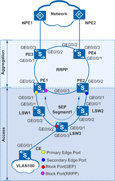
In Figure 1, multiple Layer 2 switching devices at the access layer and aggregation layer form a ring network to access the core layer. RRPP has been configured at the aggregation layer to eliminate loops. In this case, SEP needs to run at the access layer to implement the following functions:
- Eliminates loops when there is no faulty link on the ring network.
- Rapidly restores communication between nodes when a link fault occurs on the ring network.
Provides the topology change notification function on an edge device in a SEP segment. This function enables an upper-layer network to detect topology changes in a lower-layer network in time.
After receiving a message indicating the topology change in a lower-layer network, a device on an upper-layer network sends TC packets to instruct other devices to delete original MAC addresses and learn new MAC addresses after the topology of the lower-layer network changes. This ensures uninterrupted traffic forwarding.
Configuration Roadmap
The configuration roadmap is as follows:
Configure basic SEP functions.
Configure SEP segment 1 on PE1, PE2, and LSW1 to LSW3 and configure VLAN 10 as the control VLAN of SEP segment 1.
Add PE1, PE2, and LSW1 to LSW3 to SEP segment 1, and configure interface roles on edge devices (PE1 and PE2) of the SEP segment.
Set an interface blocking mode on the device where a primary edge interface is located to specify an interface to block.
Configure the preemption mode to ensure that the specified interface is blocked when a fault is rectified.
Configure the topology change notification function so that the topology change in the local SEP segment can be notified to the upper-layer network where RRPP is enabled.
Configure basic RRPP functions.
Add PE1 to PE4 to RRPP domain 1, create control VLAN 5 on PE1 to PE4, and configure a protected VLAN.
Configure PE1 as the master node and PE2 to PE4 as transit nodes on the major ring, and configure the primary and secondary interfaces of the major ring.
Create a VLAN on PE1 to PE4, and add the interfaces on the RRPP ring network to the VLAN.
- Configure the Layer 2 forwarding function on the CE, LSW1 to LSW3, and PE1 to PE4.
Procedure
- Configure basic SEP functions.
Configure SEP segment 1 on PE1, PE2, and LSW1 to LSW3 and configure VLAN 10 as the control VLAN of SEP segment 1.
# Configure PE1.
<HUAWEI> system-view[HUAWEI] sysname PE1[PE1] sep segment 1
[PE1-sep-segment1] control-vlan 10
[PE1-sep-segment1] protected-instance all
[PE1-sep-segment1] quit
# Configure PE2.
<HUAWEI> system-view[HUAWEI] sysname PE2[PE2] sep segment 1
[PE2-sep-segment1] control-vlan 10
[PE2-sep-segment1] protected-instance all
[PE2-sep-segment1] quit
# Configure LSW1.<HUAWEI> system-view[HUAWEI] sysname LSW1[LSW1] sep segment 1
[LSW1-sep-segment1] control-vlan 10
[LSW1-sep-segment1] protected-instance all
[LSW1-sep-segment1] quit
# Configure LSW2.<HUAWEI> system-view[HUAWEI] sysname LSW2[LSW2] sep segment 1
[LSW2-sep-segment1] control-vlan 10
[LSW2-sep-segment1] protected-instance all
[LSW2-sep-segment1] quit
# Configure LSW3.<HUAWEI> system-view[HUAWEI] sysname LSW3[LSW3] sep segment 1
[LSW3-sep-segment1] control-vlan 10
[LSW3-sep-segment1] protected-instance all
[LSW3-sep-segment1] quit
Add PE1, PE2, and LSW1 to LSW3 to SEP segment 1 and configure interface roles.

By default, STP is enabled on an interface. Before adding an interface to a SEP segment, disable STP on the interface.
# Configure PE1.
[PE1] interface gigabitethernet 0/0/1
[PE1-GigabitEthernet0/0/1] port link-type trunk
[PE1-GigabitEthernet0/0/1] stp disable
[PE1-GigabitEthernet0/0/1] sep segment 1 edge primary
[PE1-GigabitEthernet0/0/1] quit
# Configure LSW1.
[LSW1] interface gigabitethernet 0/0/1
[LSW1-GigabitEthernet0/0/1] port link-type trunk
[LSW1-GigabitEthernet0/0/1] stp disable
[LSW1-GigabitEthernet0/0/1] sep segment 1
[LSW1-GigabitEthernet0/0/1] quit
[LSW1] interface gigabitethernet 0/0/2
[LSW1-GigabitEthernet0/0/2] port link-type trunk
[LSW1-GigabitEthernet0/0/2] stp disable
[LSW1-GigabitEthernet0/0/2] sep segment 1
[LSW1-GigabitEthernet0/0/2] quit
# Configure LSW2.
[LSW2] interface gigabitethernet 0/0/1
[LSW2-GigabitEthernet0/0/1] port link-type trunk
[LSW2-GigabitEthernet0/0/1] stp disable
[LSW2-GigabitEthernet0/0/1] sep segment 1
[LSW2-GigabitEthernet0/0/1] quit
[LSW2] interface gigabitethernet 0/0/2
[LSW2-GigabitEthernet0/0/2] port link-type trunk
[LSW2-GigabitEthernet0/0/2] stp disable
[LSW2-GigabitEthernet0/0/2] sep segment 1
[LSW2-GigabitEthernet0/0/2] quit
# Configure LSW3.
[LSW3] interface gigabitethernet 0/0/1
[LSW3-GigabitEthernet0/0/1] port link-type trunk
[LSW3-GigabitEthernet0/0/1] stp disable
[LSW3-GigabitEthernet0/0/1] sep segment 1
[LSW3-GigabitEthernet0/0/1] quit
[LSW3] interface gigabitethernet 0/0/2
[LSW3-GigabitEthernet0/0/2] port link-type trunk
[LSW3-GigabitEthernet0/0/2] stp disable
[LSW3-GigabitEthernet0/0/2] sep segment 1
[LSW3-GigabitEthernet0/0/2] quit
# Configure PE2.
[PE2] interface gigabitethernet 0/0/1
[PE2-GigabitEthernet0/0/1] port link-type trunk
[PE2-GigabitEthernet0/0/1] stp disable
[PE2-GigabitEthernet0/0/1] sep segment 1 edge secondary
[PE2-GigabitEthernet0/0/1] quit
After completing the preceding configurations, run the display sep topology command on PE1 to view the topology of the SEP segment. The command output shows that the blocked interface is one of the two interfaces that complete neighbor negotiations last.
[PE1] display sep topology
SEP segment 1
-------------------------------------------------------------------------
System Name          Port Name        Port Role       Port Status     Hop
-------------------------------------------------------------------------
PE1                  GE0/0/1          primary         forwarding      1
LSW1                 GE0/0/1          common          forwarding      2
LSW1                 GE0/0/2          common          forwarding      3
LSW3                 GE0/0/2          common          forwarding      4
LSW3                 GE0/0/1          common          forwarding      5
LSW2                 GE0/0/2          common          forwarding      6
LSW2                 GE0/0/1          common          forwarding      7
PE2                  GE0/0/1          secondary       discarding      8
Set an interface blocking mode.
# In SEP segment 1, block the interface in the middle of the SEP segment on PE1 where the primary edge interface resides.
[PE1] sep segment 1
[PE1-sep-segment1] block port middle
Set the preemption mode.
# In SEP segment 1, set manual preemption on PE1 where the primary edge interface resides.
[PE1-sep-segment1] preempt manual
Configure the topology change notification function.
# Configure devices in SEP segment 1 to notify topology changes to the RRPP ring network.
# Configure PE1.
[PE1-sep-segment1] tc-notify rrpp
[PE1-sep-segment1] quit
# Configure PE2.
[PE2] sep segment 1
[PE2-sep-segment1] tc-notify rrpp
[PE2-sep-segment1] quit
After the preceding configurations are successful, perform the following operations to verify the configurations. PE1 is used as an example.
Run the display sep topology command on PE1 to view the topology of the SEP segment.
The command output shows that the status of GE 0/0/2 on LSW3 is discarding and the status of the other interfaces is forwarding.
[PE1] display sep topology
SEP segment 1
-------------------------------------------------------------------------
System Name          Port Name        Port Role       Port Status     Hop
-------------------------------------------------------------------------
PE1                  GE0/0/1          primary         forwarding      1
LSW1                 GE0/0/1          common          forwarding      2
LSW1                 GE0/0/2          common          forwarding      3
LSW3                 GE0/0/2          common          discarding      4
LSW3                 GE0/0/1          common          forwarding      5
LSW2                 GE0/0/2          common          forwarding      6
LSW2                 GE0/0/1          common          forwarding      7
PE2                  GE0/0/1          secondary       forwarding      8
Run the display sep interface verbose command on PE1 to view detailed information about the interfaces added to the SEP segment.
[PE1] display sep interface verbose
SEP segment 1
Control-vlan             :10
Preempt Delay Timer      :0
TC-Notify Propagate to :rrpp
----------------------------------------------------------------
Interface              :GE0/0/1
Port Role              :Config = primary / Active =  primary
Port Priority          :64
Port Status            :forwarding
Neighbor Status        :up
Neighbor Port          :LSW1 - GE0/0/1 (00e0-0829-7c00.0000)
NBR TLV             rx :2124             tx :2126
LSP INFO TLV        rx :2939             tx :135
LSP ACK TLV         rx :113              tx :768
PREEMPT REQ TLV     rx :0                tx :3
PREEMPT ACK TLV     rx :3                tx :0
TC Notify           rx :5                tx :3
EPA                 rx :363              tx :397
- Configure basic RRPP functions.
Add PE1 to PE4 to RRPP domain 1, create control VLAN 5 on PE1 to PE4, and configure a protected VLAN.
# Configure PE1.
[PE1] stp region-configuration
[PE1-mst-region] instance 1 vlan 5 6 100
[PE1-mst-region] active region-configuration
[PE1-mst-region] quit
[PE1] rrpp domain 1
[PE1-rrpp-domain-region1] control-vlan 5
[PE1-rrpp-domain-region1] protected-vlan reference-instance 1
# Configure PE2.
[PE2] stp region-configuration
[PE2-mst-region] instance 1 vlan 5 6 100
[PE2-mst-region] active region-configuration
[PE2-mst-region] quit
[PE2] rrpp domain 1
[PE2-rrpp-domain-region1] control-vlan 5
[PE2-rrpp-domain-region1] protected-vlan reference-instance 1
# Configure PE3.
[PE3] stp region-configuration
[PE3-mst-region] instance 1 vlan 5 6 100
[PE3-mst-region] active region-configuration
[PE3-mst-region] quit
[PE3] rrpp domain 1
[PE3-rrpp-domain-region1] control-vlan 5
[PE3-rrpp-domain-region1] protected-vlan reference-instance 1
# Configure PE4.
[PE4] stp region-configuration
[PE4-mst-region] instance 1 vlan 5 6 100
[PE4-mst-region] active region-configuration
[PE4-mst-region] quit
[PE4] rrpp domain 1
[PE4-rrpp-domain-region1] control-vlan 5
[PE4-rrpp-domain-region1] protected-vlan reference-instance 1
Create a VLAN and add interfaces on the ring network to the VLAN.
# Create VLAN 100 on PE1, and add GE 0/0/1, GE 0/0/2, and GE 0/0/3 to VLAN 100.
[PE1] vlan 100
[PE1-vlan100] quit
[PE1] interface gigabitethernet 0/0/1
[PE1-GigabitEthernet0/0/1] stp disable
[PE1-GigabitEthernet0/0/1] port link-type trunk
[PE1-GigabitEthernet0/0/1] port trunk allow-pass vlan 100
[PE1-GigabitEthernet0/0/1] quit
[PE1] interface gigabitethernet 0/0/2
[PE1-GigabitEthernet0/0/2] stp disable
[PE1-GigabitEthernet0/0/2] port link-type trunk
[PE1-GigabitEthernet0/0/2] port trunk allow-pass vlan 100
[PE1-GigabitEthernet0/0/2] quit
[PE1] interface gigabitethernet 0/0/3
[PE1-GigabitEthernet0/0/3] stp disable
[PE1-GigabitEthernet0/0/3] port link-type trunk
[PE1-GigabitEthernet0/0/3] port trunk allow-pass vlan 100
[PE1-GigabitEthernet0/0/3] quit
# Create VLAN 100 on PE2, and add GE 0/0/1, GE 0/0/2, and GE 0/0/3 to VLAN 100.
[PE2] vlan 100
[PE2-vlan100] quit
[PE2] interface gigabitethernet 0/0/1
[PE2-GigabitEthernet0/0/1] stp disable
[PE2-GigabitEthernet0/0/1] port link-type trunk
[PE2-GigabitEthernet0/0/1] port trunk allow-pass vlan 100
[PE2-GigabitEthernet0/0/1] quit
[PE2] interface gigabitethernet 0/0/2
[PE2-GigabitEthernet0/0/2] stp disable
[PE2-GigabitEthernet0/0/2] port link-type trunk
[PE2-GigabitEthernet0/0/2] port trunk allow-pass vlan 100
[PE2-GigabitEthernet0/0/2] quit
[PE2] interface gigabitethernet 0/0/3
[PE2-GigabitEthernet0/0/3] stp disable
[PE2-GigabitEthernet0/0/3] port link-type trunk
[PE2-GigabitEthernet0/0/3] port trunk allow-pass vlan 100
[PE2-GigabitEthernet0/0/3] quit
# Create VLAN 100 on PE3, and add GE 0/0/1 and GE 0/0/2 to VLAN 100.
[PE3] vlan 100
[PE3-vlan100] quit
[PE3] interface gigabitethernet 0/0/1
[PE3-GigabitEthernet0/0/1] stp disable
[PE3-GigabitEthernet0/0/1] port link-type trunk
[PE3-GigabitEthernet0/0/1] port trunk allow-pass vlan 100
[PE3-GigabitEthernet0/0/1] quit
[PE3] interface gigabitethernet 0/0/2
[PE3-GigabitEthernet0/0/2] stp disable
[PE3-GigabitEthernet0/0/2] port link-type trunk
[PE3-GigabitEthernet0/0/2] port trunk allow-pass vlan 100
[PE3-GigabitEthernet0/0/2] quit
# Create VLAN 100 on PE4, and add GE 0/0/1 and GE 0/0/2 to VLAN 100.
[PE4] vlan 100
[PE4-vlan100] quit
[PE4] interface gigabitethernet 0/0/1
[PE4-GigabitEthernet0/0/1] stp disable
[PE4-GigabitEthernet0/0/1] port link-type trunk
[PE4-GigabitEthernet0/0/1] port trunk allow-pass vlan 100
[PE4-GigabitEthernet0/0/1] quit
[PE4] interface gigabitethernet 0/0/2
[PE4-GigabitEthernet0/0/2] stp disable
[PE4-GigabitEthernet0/0/2] port link-type trunk
[PE4-GigabitEthernet0/0/2] port trunk allow-pass vlan 100
[PE4-GigabitEthernet0/0/2] quit
Configure PE1 as the master node and PE2 to PE4 as transit nodes on the major ring, and configure the primary and secondary interfaces of the major ring.
# Configure PE1.
[PE1] rrpp domain 1
[PE1-rrpp-domain-region1] ring 1 node-mode master primary-port gigabitethernet0/0/2 secondary-port gigabitethernet0/0/3 level 0
[PE1-rrpp-domain-region1] ring 1 enable
# Configure PE2.
[PE2] rrpp domain 1
[PE2-rrpp-domain-region1] ring 1 node-mode transit primary-port gigabitethernet0/0/2 secondary-port gigabitethernet0/0/3 level 0
[PE2-rrpp-domain-region1] ring 1 enable
# Configure PE3.
[PE3] rrpp domain 1
[PE3-rrpp-domain-region1] ring 1 node-mode transit primary-port gigabitethernet0/0/1 secondary-port gigabitethernet0/0/2 level 0
[PE3-rrpp-domain-region1] ring 1 enable
# Configure PE4.
[PE4] rrpp domain 1
[PE4-rrpp-domain-region1] ring 1 node-mode transit primary-port gigabitethernet0/0/1 secondary-port gigabitethernet0/0/2 level 0
[PE4-rrpp-domain-region1] ring 1 enable
Enable RRPP.
# Configure PE1.
[PE1] rrpp enable
# Configure PE2.
[PE2] rrpp enable
# Configure PE3.
[PE3] rrpp enable
# Configure PE4.
[PE4] rrpp enable
After completing the preceding configurations, run the display rrpp brief or display rrpp verbose domain command on PE1 to check the RRPP configuration.[PE1] display rrpp brief
Abbreviations for Switch Node Mode :
M - Master , T - Transit , E - Edge , A - Assistant-Edge

RRPP Protocol Status: Enable
RRPP Working Mode: HW
RRPP Linkup Delay Timer: 0 sec (0 sec default)
Number of RRPP Domains: 1

Domain Index   : 1
Control VLAN   : major 5    sub 6
Protected VLAN : Reference Instance 1
Hello Timer    : 1 sec(default is 1 sec)  Fail Timer : 6 sec(default is 6 sec)
 Ring  Ring   Node  Primary/Common           Secondary/Edge           Is
 ID    Level  Mode  Port                     Port                     Enabled
 ----------------------------------------------------------------------------
 1     0      M     GigabitEthernet0/0/2     GigabitEthernet0/0/3    Yes
The command output shows that RRPP is enabled on PE1. In domain 1, VLAN 5 is the major control VLAN, VLAN 6 is the sub-control VLAN, Instance 1 is the protected VLAN, and PE1 is the master node in major ring 1 with the primary and secondary interfaces as GigabitEthernet0/0/2 and GigabitEthernet0/0/3 respectively.
[PE1] display rrpp verbose domain 1
Domain Index   : 1
Control VLAN   : major 5    sub 6
Protected VLAN : Reference Instance 1
Hello Timer    : 1 sec(default is 1 sec)  Fail Timer : 6 sec(default is 6 sec)

RRPP Ring      : 1
Ring Level     : 0
Node Mode      : Master
Ring State     : Complete
Is Enabled     : Enable                             Is Active: Yes
Primary port   : GigabitEthernet0/0/2               Port status: UP
Secondary port : GigabitEthernet0/0/3               Port status: BLOCKED
The command output shows that in domain 1, VLAN 5 is the major control VLAN, VLAN 6 is the sub-control VLAN, Instance 1 is the protected VLAN, PE1 is the master node in major ring 1 with the primary and secondary interfaces as GigabitEthernet0/0/2 and GigabitEthernet0/0/3 respectively, and the node status is Complete.
- Configure the Layer 2 forwarding function on
the CE, LSW1 to LSW3, and PE1 to PE4.
For the configuration details, see the configuration files.
- Verify the configuration.
After the previous configurations, run the following commands to verify the configuration when the network is stable. LSW1 is used as an example.
Run the shutdown command on GE0/0/1 of LSW2 to simulate an interface fault, and then run the display sep interface command on LSW3 to check whether the status of GE0/0/2 changes from blocked to forwarding.
[LSW3] display sep interface gigabitethernet 0/0/2
SEP segment 1
----------------------------------------------------------------
Interface           Port Role     Neighbor Status     Port Status
----------------------------------------------------------------
GE0/0/2             common        up                  forwarding
Configuration Files
LSW1 configuration file
#
 sysname LSW1
#
 vlan batch 10 100
#
sep segment 1
 control-vlan 10
 protected-instance 0 to 48
#
interface GigabitEthernet0/0/1
 port link-type trunk
 port trunk allow-pass vlan 10 100
 stp disable
 sep segment 1
#
interface GigabitEthernet0/0/2
 port link-type trunk
 port trunk allow-pass vlan 10 100
 stp disable
 sep segment 1
#
return
LSW2 configuration file
#
 sysname LSW2
#
 vlan batch 10 100
#
sep segment 1
 control-vlan 10
 protected-instance 0 to 48
#
interface GigabitEthernet0/0/1
 port link-type trunk
 port trunk allow-pass vlan 10 100
 stp disable
 sep segment 1
#
interface GigabitEthernet0/0/2
 port link-type trunk
 port trunk allow-pass vlan 10 100
 stp disable
 sep segment 1
#
return
LSW3 configuration file
#
 sysname LSW3
#
 vlan batch 10 100
#
sep segment 1
 control-vlan 10
 protected-instance 0 to 48
#
interface GigabitEthernet0/0/1
 port link-type trunk
 port trunk allow-pass vlan 10 100
 stp disable
 sep segment 1
#
interface GigabitEthernet0/0/2
 port link-type trunk
 port trunk allow-pass vlan 10 100
 stp disable
 sep segment 1
#
interface GigabitEthernet0/0/3
 port link-type trunk
 port trunk allow-pass vlan 100
#
return
PE1 configuration file
#
 sysname PE1
#
 vlan batch 5 to 6 10 100
#
 rrpp enable
#
 stp region-configuration
  instance 1 vlan 5 to 6 100
  active region-configuration
#
rrpp domain 1
 control-vlan 5
 protected-vlan reference-instance 1
 ring 1 node-mode master primary-port GigabitEthernet 0/0/2 secondary-port GigabitEthernet 0/0/3 level 0
 ring 1 enable
#
sep segment 1
 control-vlan 10
 block port middle
 tc-notify rrpp
 protected-instance 0 to 48
#
interface GigabitEthernet0/0/1
 port link-type trunk
 port trunk allow-pass vlan 10 100
 stp disable
 sep segment 1 edge primary
#
interface GigabitEthernet0/0/2
 port link-type trunk
 port trunk allow-pass vlan 5 to 6 100
 stp disable
#
interface GigabitEthernet0/0/3
 port link-type trunk
 port trunk allow-pass vlan 5 to 6 100
 stp disable
#
return
PE2 configuration file
#
 sysname PE2
#
 vlan batch 5 to 6 10 100
#
 rrpp enable
#
 stp region-configuration
  instance 1 vlan 5 to 6 100
  active region-configuration
#
rrpp domain 1
 control-vlan 5
 protected-vlan reference-instance 1
 ring 1 node-mode transit primary-port GigabitEthernet 0/0/2 secondary-port GigabitEthernet 0/0/3 level 0
 ring 1 enable
#
sep segment 1
 control-vlan 10
 tc-notify rrpp
 protected-instance 0 to 48
#
interface GigabitEthernet0/0/1
 port link-type trunk
 port trunk allow-pass vlan 10 100
 stp disable
 sep segment 1 edge secondary
#
interface GigabitEthernet0/0/2
 port link-type trunk
 port trunk allow-pass vlan 5 to 6 100
 stp disable
#
interface GigabitEthernet0/0/3
 port link-type trunk
 port trunk allow-pass vlan 5 to 6 100
 stp disable
#
return
PE3 configuration file
#
 sysname PE3
#
 vlan batch 5 to 6 100 200
#
 rrpp enable
#
 stp region-configuration
  instance 1 vlan 5 to 6 100
  active region-configuration
#
rrpp domain 1
 control-vlan 5
 protected-vlan reference-instance 1
 ring 1 node-mode transit primary-port GigabitEthernet 0/0/1 secondary-port GigabitEthernet 0/0/2 level 0
 ring 1 enable
#
interface GigabitEthernet0/0/1
 port link-type trunk
 port trunk allow-pass vlan 100
 stp disable
#
interface GigabitEthernet0/0/2
 port link-type trunk
 port trunk allow-pass vlan 5 to 6 100 200
 stp disable
#
interface GigabitEthernet0/0/3
 port link-type trunk
 port default vlan 200
 port trunk allow-pass vlan 5 to 6 100
#
return
PE4 configuration file
#
 sysname PE4
#
 vlan batch 5 to 6 100 200
#
 rrpp enable
#
 stp region-configuration
  instance 1 vlan 5 to 6 100
  active region-configuration
#
rrpp domain 1
 control-vlan 5
 protected-vlan reference-instance 1
 ring 1 node-mode transit primary-port GigabitEthernet 0/0/1 secondary-port GigabitEthernet 0/0/2 level 0
 ring 1 enable
#
interface GigabitEthernet0/0/1
 port link-type trunk
 port trunk allow-pass vlan 100
 stp disable
#
interface GigabitEthernet0/0/2
 port link-type trunk
 port trunk allow-pass vlan 5 to 6 100 200
 stp disable
#
interface GigabitEthernet0/0/3
 port link-type trunk
 port default vlan 200
 port trunk allow-pass vlan 5 to 6 100
#
return
CE1 configuration file
#
 sysname CE1
#
 vlan batch 100
#
interface GigabitEthernet0/0/1
 port link-type trunk
 port trunk allow-pass vlan 100
#
return