Example for Configuring Load Balancing in a Smart Link Group
Networking Requirements
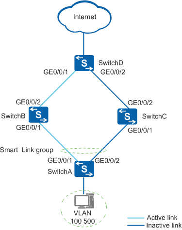
As shown in Figure 1, a dual-homing networking is used to enhance network reliability. Data flows of multiple VLANs are transmitted on the network. To use the uplinks more efficiently, the customer wants data flows to be transmitted on both uplinks and requires that the service interruption time should be restricted to the millisecond level if an uplink fails.
Configuration Roadmap
The configuration roadmap is as follows:
- Map VLAN 500 of which the traffic needs to be transmitted through the standby link to instance 10.
- Create a Smart Link group on SwitchA and add uplink interfaces to the Smart Link group.
- Configure load balancing on SwitchA to forward the data flows from the VLAN mapped to instance 10 over the standby link.
- Enable revertive switching on SwitchA to enable traffic to be switched back to the original active link after the active link recovers.
- Enable SwitchA to send Flush packets.
- Enable interfaces of SwitchB, SwitchC, and SwitchD to receive Flush packets.
- Enable the Smart Link group on SwitchA.
Procedure
- Create VLANs.
# Create VLANs on SwitchA, and configure interfaces to allow packets of these VLANs to pass through. The configurations of SwitchB, SwitchC, and SwitchD are similar to the configuration of SwitchA and are not mentioned here. For details, see the configuration files.
<HUAWEI> system-view
[HUAWEI] sysname SwitchA
[SwitchA] vlan batch 10 100 500
[SwitchA] interface gigabitethernet 0/0/1
[SwitchA-GigabitEthernet0/0/1] port link-type trunk
[SwitchA-GigabitEthernet0/0/1] port trunk allow-pass vlan 10 100 500
[SwitchA-GigabitEthernet0/0/1] quit
[SwitchA] interface gigabitethernet 0/0/2
[SwitchA-GigabitEthernet0/0/2] port link-type trunk
[SwitchA-GigabitEthernet0/0/2] port trunk allow-pass vlan 10 100 500
[SwitchA-GigabitEthernet0/0/2] quit
- Map VLAN 500 to instance 10 on SwitchA.
[SwitchA] stp region-configuration
[SwitchA-mst-region] instance 10 vlan 500
[SwitchA-mst-region] active region-configuration
[SwitchA-mst-region] quit
- Disable STP on uplink interfaces, add the interfaces to the Smart Link group, and specify the master and slave interfaces.
# Configure SwitchA.
[SwitchA] interface gigabitethernet 0/0/1
[SwitchA-GigabitEthernet0/0/1] stp disable
[SwitchA-GigabitEthernet0/0/1] quit
[SwitchA] interface gigabitethernet 0/0/2
[SwitchA-GigabitEthernet0/0/2] stp disable
[SwitchA-GigabitEthernet0/0/2] quit
[SwitchA] smart-link group 1
[SwitchA-smlk-group1] port gigabitethernet 0/0/1 master
[SwitchA-smlk-group1] port gigabitethernet 0/0/2 slave
- Configure load balancing on SwitchA.
[SwitchA-smlk-group1] load-balance instance 10 slave - Enable revertive switching and set the WTR time.
# Configure SwitchA.
[SwitchA-smlk-group1] restore enable
[SwitchA-smlk-group1] timer wtr 30
- Enable SwitchA to send Flush packets.
# Configure SwitchA to send Flush packets containing an SHA-encrypted password.
[SwitchA-smlk-group1] flush send control-vlan 10 password sha huawei-123
- Enable interfaces of SwitchB, SwitchC, and SwitchD to receive Flush packets.
# Enable SwitchB to receive Flush packets containing an SHA-encrypted password.
[SwitchB] interface gigabitethernet 0/0/1
[SwitchB-GigabitEthernet0/0/1] smart-link flush receive control-vlan 10 password sha huawei-123
[SwitchB-GigabitEthernet0/0/1] stp disable
[SwitchB-GigabitEthernet0/0/1] quit
[SwitchB] interface gigabitethernet 0/0/2
[SwitchB-GigabitEthernet0/0/2] smart-link flush receive control-vlan 10 password sha huawei-123
[SwitchB-GigabitEthernet0/0/2] stp disable
[SwitchB-GigabitEthernet0/0/2] quit
# Enable SwitchC to receive Flush packets containing an SHA-encrypted password.
[SwitchC] interface gigabitethernet 0/0/1
[SwitchC-GigabitEthernet0/0/1] smart-link flush receive control-vlan 10 password sha huawei-123
[SwitchC-GigabitEthernet0/0/1] stp disable
[SwitchC-GigabitEthernet0/0/1] quit
[SwitchC] interface gigabitethernet 0/0/2
[SwitchC-GigabitEthernet0/0/2] smart-link flush receive control-vlan 10 password sha huawei-123
[SwitchC-GigabitEthernet0/0/2] stp disable
[SwitchC-GigabitEthernet0/0/2] quit
# Enable SwitchD to receive Flush packets containing an SHA-encrypted password.
[SwitchD] interface gigabitethernet 0/0/1
[SwitchD-GigabitEthernet0/0/1] smart-link flush receive control-vlan 10 password sha huawei-123
[SwitchD-GigabitEthernet0/0/1] stp disable
[SwitchD-GigabitEthernet0/0/1] quit
[SwitchD] interface gigabitethernet 0/0/2
[SwitchD-GigabitEthernet0/0/2] smart-link flush receive control-vlan 10 password sha huawei-123
[SwitchD-GigabitEthernet0/0/2] stp disable
[SwitchD-GigabitEthernet0/0/2] quit
- Enable the Smart Link group on SwitchA.
[SwitchA-smlk-group1] smart-link enable
[SwitchA-smlk-group1] quit
- Verify the configuration.
# Run the display smart-link group command to view information about the Smart Link group on SwitchA. If the following information is displayed, the configuration is successful:
- The Smart Link function is enabled.
- The WTR time is 30 seconds.
- The control VLAN ID is 10.
- GE 0/0/1 is the master interface and is in Active state, whereas GE 0/0/2 is the slave interface and is in Inactive state.
[SwitchA] display smart-link group 1
Smart Link group 1 information :
  Smart Link group was enabled
  Wtr-time is: 30 sec.
  Load-Balance Instance: 10
  There is no protected-vlan reference-instance
  DeviceID: 0018-2000-0083  Control-vlan ID: 10
  Member                  Role   InstanceID State    Flush Count Last-Flush-Time
  ---------------------------------------------------------------------------------

  GigabitEthernet0/0/1    Master 0          Active   1           2009/01/05 10:33:46 UTC+05:00
  GigabitEthernet0/0/1    Master 10         Inactive 1           2009/01/05 10:33:46 UTC+05:00
  GigabitEthernet0/0/2    Slave  0          Inactive 0           0000/00/00 00:00:00 UTC+05:00
  GigabitEthernet0/0/2    Slave  10         Active   0           0000/00/00 00:00:00 UTC+05:00
# Run the shutdown command to shut down GE 0/0/1. Then, GE 0/0/1 changes to Inactive state, and GE 0/0/2 changes to Active state.
[SwitchA] interface gigabitethernet 0/0/1
[SwitchA-GigabitEthernet0/0/1] shutdown
[SwitchA-GigabitEthernet0/0/1] display smart-link group 1
Smart Link group 1 information :
  Smart Link group was enabled
  Wtr-time is: 30 sec.
  Load-Balance Instance: 10
  There is no protected-vlan reference-instance
  DeviceID: 0018-2000-0083  Control-vlan ID: 10
  Member                  Role   InstanceID State    Flush Count Last-Flush-Time
  ---------------------------------------------------------------------------------

  GigabitEthernet0/0/1    Master 0          Inactive 1           2009/01/05 10:33:46 UTC+05:00
  GigabitEthernet0/0/1    Master 10         Inactive 1           2009/01/05 10:33:46 UTC+05:00
  GigabitEthernet0/0/2    Slave  0          Active   1           2009/01/05 10:34:46 UTC+05:00
  GigabitEthernet0/0/2    Slave  10         Active   1           2009/01/05 10:34:46 UTC+05:00
# Run the undo shutdown command to restore GE 0/0/1.
[SwitchA-GigabitEthernet0/0/1] undo shutdown
After 30 seconds, GE 0/0/1 is in Active state, and GE 0/0/2 is in Inactive state.
[SwitchA-GigabitEthernet0/0/1] display smart-link group 1
Smart Link group 1 information :
  Smart Link group was enabled
  Wtr-time is: 30 sec.
  Load-Balance Instance: 10
  There is no protected-vlan reference-instance
  DeviceID: 0018-2000-0083  Control-vlan ID: 10
  Member                  Role   InstanceID State    Flush Count Last-Flush-Time
  ---------------------------------------------------------------------------------

  GigabitEthernet0/0/1    Master 0          Active   2           2009/01/05 10:35:46 UTC+05:00
  GigabitEthernet0/0/1    Master 10         Inactive 2           2009/01/05 10:35:46 UTC+05:00
  GigabitEthernet0/0/2    Slave  0          Inactive 1           2009/01/05 10:34:46 UTC+05:00
  GigabitEthernet0/0/2    Slave  10         Active   1           2009/01/05 10:34:46 UTC+05:00
# Assume that PC1 belongs to VLAN 100 and PC2 belongs to VLAN 500. PC1 and PC2 can access the Internet.
Configuration Files
SwitchA configuration file
#
sysname SwitchA
#
vlan batch 10 100 500
#
stp region-configuration
 instance 10 vlan 500
 active region-configuration
#
interface GigabitEthernet0/0/1
 port link-type trunk
 port trunk allow-pass vlan 10 100 500
 stp disable
#
interface GigabitEthernet0/0/2
 port link-type trunk
 port trunk allow-pass vlan 10 100 500
 stp disable
#
smart-link group 1
 load-balance instance 10 slave
 restore enable
 smart-link enable
 port GigabitEthernet0/0/1 master
 port GigabitEthernet0/0/2 slave
 timer wtr 30
 flush send control-vlan 10 password sha %^%#rwIhOw`~g7,xyl>~|:v9Cyw2CH,7l2\dbzA[cH3YA9BdA;1qqSs%WJHM3|hO%^%#
#
return
SwitchB configuration file
#
sysname SwitchB
#
vlan batch 10 100 500
#
interface GigabitEthernet0/0/1
 port link-type trunk
 port trunk allow-pass vlan 10 100 500
 stp disable
 smart-link flush receive control-vlan 10 password sha %^%#fR)IGHHT:>]iNbG:Nq#)<^1p#`np!T#/\V&%)iHB_ibX!99]e#E{/L2Sxw!I%^%#
#
interface GigabitEthernet0/0/2
 port link-type trunk
 port trunk allow-pass vlan 10 100 500
 stp disable
 smart-link flush receive control-vlan 10 password sha %^%#XbPxG#g5C6$/*d2^GRU>3ODTJF_C(Bht`^*}tT05u]7SIZ5y%9bQ!x~3:v;O%^%#
#
return
SwitchC configuration file
#
sysname SwitchC
#
vlan batch 10 100 500
#
interface GigabitEthernet0/0/1
 port link-type trunk
 port trunk allow-pass vlan 10 100 500
 stp disable
 smart-link flush receive control-vlan 10 password sha %^%#IOf[Q`=F=QK"O4-j9A}Y-N7<,F~cn%/NR:G-,L5*[SMN,FlIYAZd88*ObE;T%^%#
#
interface GigabitEthernet0/0/2
 port link-type trunk
 port trunk allow-pass vlan 10 100 500
 stp disable
 smart-link flush receive control-vlan 10 password sha %^%#vMK'GvJozEo1Fi:%~jkO<ge&0HgYZVh@ch709e49'r8&M{k6X.NzX)<K_R<P%^%#
#
return
SwitchD configuration file
#
sysname SwitchD
#
vlan batch 10 100 500
#
interface GigabitEthernet0/0/1
 port link-type trunk
 port trunk allow-pass vlan 10 100 500
 stp disable
 smart-link flush receive control-vlan 10 password sha %^%#:ssvXl%=T&UGOl$eoPWJaQ'>)@+TbEELAQM=7sh~J1>;>,H<HIEjK$@kW1B1%^%#
#
interface GigabitEthernet0/0/2
 port link-type trunk
 port trunk allow-pass vlan 10 100 500
 stp disable
 smart-link flush receive control-vlan 10 password sha %^%#i~K431w:TERjN]OK0kS+Y*VB=*-BP2+X33UoHVG#{<qPBD:s1.~,2h/s($\&%^%#
#
return