Example for Combining Monitor Link and Smart Link on a Network
Networking Requirements
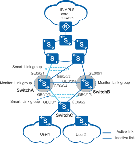
As shown in Figure 1, SwitchC is connected to user networks and is dual-homed to SwitchA and SwitchB, which are connected to the backbone network.
A monitoring mechanism is required to prevent service interruption caused by uplink failures. If an uplink fails, the downlinks can rapidly detect the failure and trigger link switching immediately to minimize the service interruption time.
Configuration Roadmap
The configuration roadmap is as follows:
- Configure a Smart Link group on SwitchA and SwitchC and add corresponding interfaces to the Smart Link groups.
- Enable SwitchA and SwitchC to send Flush packets.
- Enable SwitchA and SwitchB to receive Flush packets.
- Configure a Monitor Link group on SwitchA and configure the Smart Link group as an uplink. In this way, the Smart Link group improves the uplink reliability in the Monitor Link group.
- Configure a Monitor Link group on SwitchB to enable the Smart Link group on SwitchC to rapidly detect uplink failures. This configuration widens the application scope of Smart Link.
Procedure
- Configure the control VLAN on SwitchA, SwitchB, and SwitchC. Add the interfaces of the Smart Link or Monitor Link groups to this VLAN.
# Configure SwitchA. The configurations of SwitchB and SwitchC are similar to the configuration of SwitchA, and are not mentioned here. For details, see the configuration files.
<HUAWEI> system-view
[HUAWEI] sysname SwitchA
[SwitchA] vlan batch 10
[SwitchA] interface gigabitethernet 0/0/1
[SwitchA-GigabitEthernet0/0/1] port link-type trunk
[SwitchA-GigabitEthernet0/0/1] port trunk allow-pass vlan 10
[SwitchA-GigabitEthernet0/0/1] quit
[SwitchA] interface gigabitethernet 0/0/2
[SwitchA-GigabitEthernet0/0/2] port link-type trunk
[SwitchA-GigabitEthernet0/0/2] port trunk allow-pass vlan 10
[SwitchA-GigabitEthernet0/0/2] quit
[SwitchA] interface gigabitethernet 0/0/3
[SwitchA-GigabitEthernet0/0/3] port link-type trunk
[SwitchA-GigabitEthernet0/0/3] port trunk allow-pass vlan 10
[SwitchA-GigabitEthernet0/0/3] quit
[SwitchA] interface gigabitethernet 0/0/4
[SwitchA-GigabitEthernet0/0/4] port link-type trunk
[SwitchA-GigabitEthernet0/0/4] port trunk allow-pass vlan 10
[SwitchA-GigabitEthernet0/0/4] quit
- Create Smart Link groups.
# Configure SwitchA.
[SwitchA] smart-link group 1
[SwitchA-smlk-group1] quit
# Configure SwitchC.
[SwitchC] smart-link group 2
[SwitchC-smlk-group2] quit
- Add interfaces to the Smart Link groups and specify the master and slave interfaces.
# Configure SwitchA.
[SwitchA] interface gigabitethernet 0/0/1
[SwitchA-GigabitEthernet0/0/1] stp disable
[SwitchA-GigabitEthernet0/0/1] quit
[SwitchA] interface gigabitethernet 0/0/2
[SwitchA-GigabitEthernet0/0/2] stp disable
[SwitchA-GigabitEthernet0/0/2] quit
[SwitchA] smart-link group 1
[SwitchA-smlk-group1] port gigabitethernet 0/0/1 master
[SwitchA-smlk-group1] port gigabitethernet 0/0/2 slave
# Configure SwitchC.
[SwitchC] interface gigabitethernet 0/0/1
[SwitchC-GigabitEthernet0/0/1] stp disable
[SwitchC-GigabitEthernet0/0/1] quit
[SwitchC] interface gigabitethernet 0/0/2
[SwitchC-GigabitEthernet0/0/2] stp disable
[SwitchC-GigabitEthernet0/0/2] quit
[SwitchC] smart-link group 2
[SwitchC-smlk-group2] port gigabitethernet 0/0/1 master
[SwitchC-smlk-group2] port gigabitethernet 0/0/2 slave
- Enable revertive switching and set the WTR time.
# Configure SwitchA.
[SwitchA-smlk-group1] restore enable
[SwitchA-smlk-group1] timer wtr 30
# Configure SwitchC.
[SwitchC-smlk-group2] restore enable
[SwitchC-smlk-group2] timer wtr 30
- Enable SwitchA and SwitchC to send Flush packets, and enable SwitchA and SwitchB to receive Flush packets.
# Configure SwitchA to send and receive Flush packets containing an SHA-encrypted password.
[SwitchA-smlk-group1] flush send control-vlan 10 password sha huawei-123
[SwitchA-smlk-group1] quit
[SwitchA] interface gigabitethernet 0/0/3
[SwitchA-GigabitEthernet0/0/3] smart-link flush receive control-vlan 10 password sha huawei-123
[SwitchA-GigabitEthernet0/0/3] stp disable
[SwitchA-GigabitEthernet0/0/3] quit
[SwitchA] interface gigabitethernet 0/0/4
[SwitchA-GigabitEthernet0/0/4] smart-link flush receive control-vlan 10 password sha huawei-123
[SwitchA-GigabitEthernet0/0/4] stp disable
[SwitchA-GigabitEthernet0/0/4] quit
# Configure SwitchB to receive Flush packets containing an SHA-encrypted password.
[SwitchB] interface gigabitethernet 0/0/3
[SwitchB-GigabitEthernet0/0/3] smart-link flush receive control-vlan 10 password sha huawei-123
[SwitchB-GigabitEthernet0/0/3] stp disable
[SwitchB-GigabitEthernet0/0/3] quit
[SwitchB] interface gigabitethernet 0/0/4
[SwitchB-GigabitEthernet0/0/4] smart-link flush receive control-vlan 10 password sha huawei-123
[SwitchB-GigabitEthernet0/0/4] stp disable
[SwitchB-GigabitEthernet0/0/4] quit
# Configure SwitchC to receive Flush packets containing an SHA-encrypted password.
[SwitchC-smlk-group2] flush send control-vlan 10 password sha huawei-123
[SwitchC-smlk-group2] quit
- Enable the Smart Link group.
# Configure SwitchA.
[SwitchA] smart-link group 1
[SwitchA-smlk-group1] smart-link enable
[SwitchA-smlk-group1] quit
# Configure SwitchC.
[SwitchC] smart-link group 2
[SwitchC-smlk-group2] smart-link enable
[SwitchC-smlk-group2] quit
- Create a Monitor Link group and add uplink and downlink interfaces to the Monitor Link group.
# Configure SwitchA.
[SwitchA] monitor-link group 1
[SwitchA-mtlk-group1] smart-link group 1 uplink
[SwitchA-mtlk-group1] port gigabitethernet 0/0/3 downlink 1
# Configure SwitchB.
[SwitchB] monitor-link group 2
[SwitchB-mtlk-group2] port gigabitethernet 0/0/1 uplink
[SwitchB-mtlk-group2] port gigabitethernet 0/0/3 downlink 1
- Set the WTR time of the Monitor Link group.
# Configure SwitchA.
[SwitchA-mtlk-group1] timer recover-time 10
[SwitchA-mtlk-group1] quit
# Configure SwitchB.
[SwitchB-mtlk-group2] timer recover-time 10
[SwitchB-mtlk-group2] quit
- Verify the configuration.
[SwitchA] display smart-link group 1
Smart Link group 1 information :
  Smart Link group was enabled
  Wtr-time is: 30 sec.
  There is no Load-Balance
  There is no protected-vlan reference-instance
  DeviceID: 0018-2000-0083  Control-vlan ID: 10
  Member                  Role   InstanceID State    Flush Count Last-Flush-Time
  ---------------------------------------------------------------------------------

  GigabitEthernet0/0/1    Master 0          Active   1           0000/00/00 00:00:00 UTC+05:00
  GigabitEthernet0/0/2    Slave  0          Inactive 0           0000/00/00 00:00:00 UTC+05:00
[SwitchA] display monitor-link group 1
Monitor Link group 1 information :
  Recover-timer is 10 sec.
    Member              Role     State Last-up-time                       Last-down-time
 Smart-link1            UpLk     UP    0000/00/00 00:00:00 UTC+05:00      0000/00/00 00:00:00 UTC+05:00
 GigabitEthernet0/0/3   DwLk[1]  UP    0000/00/00 00:00:00 UTC+05:00      0000/00/00 00:00:00 UTC+05:00
Configuration Files
SwitchA configuration file
#
sysname SwitchA
#
vlan batch 10
#
interface GigabitEthernet0/0/1
 port link-type trunk
 port trunk allow-pass vlan 10
 stp disable
#
interface GigabitEthernet0/0/2
 port link-type trunk
 port trunk allow-pass vlan 10
 stp disable
#
interface GigabitEthernet0/0/3
 port link-type trunk
 port trunk allow-pass vlan 10
 stp disable
 smart-link flush receive control-vlan 10 password sha %^%#rwIhOw`~g7,xyl>~|:v9Cyw2CH,7l2\dbzA[cH3YA9BdA;1qqSs%WJHM3|hO%^%#
#
interface GigabitEthernet0/0/4
 port link-type trunk
 port trunk allow-pass vlan 10
 stp disable
 smart-link flush receive control-vlan 10 password sha %^%#fR)IGHHT:>]iNbG:Nq#)<^1p#`np!T#/\V&%)iHB_ibX!99]e#E{/L2Sxw!I%^%#
#
smart-link group 1
 restore enable
 smart-link enable
 port GigabitEthernet0/0/1 master
 port GigabitEthernet0/0/2 slave
 timer wtr 30
 flush send control-vlan 10 password sha %^%#XbPxG#g5C6$/*d2^GRU>3ODTJF_C(Bht`^*}tT05u]7SIZ5y%9bQ!x~3:v;O%^%#
#
monitor-link group 1
 smart-link group 1 uplink
 port GigabitEthernet0/0/3 downlink 1
 timer recover-time 10
#
return
SwitchB configuration file
#
sysname SwitchB
#
vlan batch 10
#
interface GigabitEthernet0/0/1
 port link-type trunk
 port trunk allow-pass vlan 10
#
interface GigabitEthernet0/0/3
 port link-type trunk
 port trunk allow-pass vlan 10
 stp disable
 smart-link flush receive control-vlan 10 password sha %^%#IOf[Q`=F=QK"O4-j9A}Y-N7<,F~cn%/NR:G-,L5*[SMN,FlIYAZd88*ObE;T%^%#
#
interface GigabitEthernet0/0/4
 port link-type trunk
 port trunk allow-pass vlan 10
 stp disable
 smart-link flush receive control-vlan 10 password sha %^%#vMK'GvJozEo1Fi:%~jkO<ge&0HgYZVh@ch709e49'r8&M{k6X.NzX)<K_R<P%^%#
#
monitor-link group 2
 port GigabitEthernet0/0/1 uplink
 port GigabitEthernet0/0/3 downlink 1
 timer recover-time 10
#
return
SwitchC configuration file
#
sysname SwitchC
#
vlan batch 10
#
interface GigabitEthernet0/0/1
 port link-type trunk
 port trunk allow-pass vlan 10
 stp disable
#
interface GigabitEthernet0/0/2
 port link-type trunk
 port trunk allow-pass vlan 10
 stp disable
#
smart-link group 2
 restore enable
 smart-link enable
 port GigabitEthernet0/0/1 master
 port GigabitEthernet0/0/2 slave
 timer wtr 30
 flush send control-vlan 10 password sha %^%#:ssvXl%=T&UGOl$eoPWJaQ'>)@+TbEELAQM=7sh~J1>;>,H<HIEjK$@kW1B1%^%#
#
return