Example for Configuring Smart Link to Notify the VPLS Module of Link Switching
Networking Requirements

Only the S5720-EI, S5720-HI, S5730-HI, S5731-H, S5731-S, S5731S-H, S5731S-S, S5732-H, S6720-EI, S6720-HI, S6720S-EI, S6730-H, S6730S-H, S6730-S, and S6730S-S support this function.
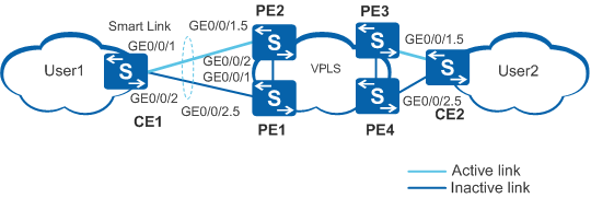
As shown in Figure 1, CE1 is dual-homed to a VPLS network through Dot1q sub-interfaces of PE2 and PE1. The Smart Link protocol runs between the two uplink interfaces of CE1. Normally, only the active link transmits service data.
If the active link fails, Smart Link unblocks the blocked interface to enable service data to be transmitted to the connected PE through this interface. A mechanism is required to notify the VPLS module of the link switching so that the VPLS module can clear forwarding entries in the local VSI and trigger other devices to clear forwarding entries in the corresponding VSI. In this way, service traffic sent from CE2 can be forwarded through the correct links.
Configuration Roadmap
The configuration roadmap is as follows:
- Configure the VPLS network.
- Configure a Smart Link group on CE1 and configure uplinks to enable CE 1 to be dual-homed to the VPLS network through PE1 and PE2.
- Enable revertive switching on CE1 to enable traffic to be switched back to the original active link after the active link recovers.
- Enable CE1 to send Flush packets.
- Enable interfaces of PE1 and PE2 to receive Flush packets, and enable the interfaces to notify the VPLS module after receiving Flush packets. In this manner, CE2 on the peer network can rapidly detect changes in the network to which CE1 is connected.
- Enable the Smart Link group on CE1.
Procedure
- Configure the VPLS network on PE1, PE2, PE3, and PE4.
For details about the configuration, see VPLS Configuration in the S2720, S5700, and S6700 V200R019C10 Configuration Guide - VPN.
- Connect the Dot1q sub-interfaces to the VPLS network.
For details about the configuration, see QinQ Configuration in the S2720, S5700, and S6700 V200R019C10 Configuration Guide - Ethernet Switching.
- Create a VLAN on CE1 and add uplink interfaces to the VLAN.
<HUAWEI> system-view
[HUAWEI] sysname CE1
[CE1] vlan batch 10
[CE1] interface gigabitethernet 0/0/1
[CE1-GigabitEthernet0/0/1] port link-type trunk
[CE1-GigabitEthernet0/0/1] port trunk allow-pass vlan 10
[CE1-GigabitEthernet0/0/1] quit
[CE1] interface gigabitethernet 0/0/2
[CE1-GigabitEthernet0/0/2] port link-type trunk
[CE1-GigabitEthernet0/0/2] port trunk allow-pass vlan 10
[CE1-GigabitEthernet0/0/2] quit
- Create the same VLAN on PE1 and PE2, and add downlink interfaces
to the VLAN.
<HUAWEI> system-view
[HUAWEI] sysname PE1
[PE1] vlan batch 10
[PE1] interface gigabitethernet 0/0/1
[PE1-GigabitEthernet0/0/1] port link-type trunk
[PE1-GigabitEthernet0/0/1] port trunk allow-pass vlan 10
[PE1-GigabitEthernet0/0/1] quit
[PE1] interface gigabitethernet 0/0/2
[PE1-GigabitEthernet0/0/2] port link-type trunk
[PE1-GigabitEthernet0/0/2] port trunk allow-pass vlan 10
[PE1-GigabitEthernet0/0/2] quit
<HUAWEI> system-view
[HUAWEI] sysname PE2
[PE2] vlan batch 10
[PE2] interface gigabitethernet 0/0/1
[PE2-GigabitEthernet0/0/1] port link-type trunk
[PE2-GigabitEthernet0/0/1] port trunk allow-pass vlan 10
[PE2-GigabitEthernet0/0/1] quit
[PE2] interface gigabitethernet 0/0/2
[PE2-GigabitEthernet0/0/2] port link-type trunk
[PE2-GigabitEthernet0/0/2] port trunk allow-pass vlan 10
[PE2-GigabitEthernet0/0/2] quit
- Disable STP on uplink interfaces of CE1, add the interfaces
to the Smart Link group, and specify the master and slave interfaces.
# Disable STP on uplink interfaces of CE1.
[CE1] interface gigabitethernet 0/0/1
[CE1-GigabitEthernet0/0/1] stp disable
[CE1-GigabitEthernet0/0/1] quit
[CE1] interface gigabitethernet 0/0/2
[CE1-GigabitEthernet0/0/2] stp disable
[CE1-GigabitEthernet0/0/2] quit
# Specify the master and slave interfaces in the Smart Link group.
[CE1] smart-link group 1
[CE1-smlk-group1] port gigabitethernet 0/0/1 master
[CE1-smlk-group1] port gigabitethernet 0/0/2 slave
- Enable revertive switching and set the WTR time.
[CE1-smlk-group1] restore enable
[CE1-smlk-group1] timer wtr 30
- Enable CE1 to send Flush packets containing an SHA-encrypted
password.
[CE1-smlk-group1] flush send control-vlan 10 password sha huawei-123
- Enable PE1 and PE2 to receive Flush packets and enable
the interfaces to notify the VPLS module after receiving Flush packets.
# Enable PE1 to receive Flush packets containing an SHA-encrypted password.
[PE1] interface gigabitethernet 0/0/2
[PE1-GigabitEthernet0/0/2] smart-link flush receive control-vlan 10 password sha huawei-123
[PE1-GigabitEthernet0/0/2] stp disable
[PE1-GigabitEthernet0/0/2] smart-link vpls-notify enable
[PE1-GigabitEthernet0/0/2] quit
[PE1] interface gigabitethernet 0/0/1
[PE1-GigabitEthernet0/0/1] smart-link flush receive control-vlan 10 password sha huawei-123
[PE1-GigabitEthernet0/0/1] stp disable
[PE1-GigabitEthernet0/0/1] quit
# Enable PE2 to receive Flush packets containing an SHA-encrypted password.
[PE2] interface gigabitethernet 0/0/1
[PE2-GigabitEthernet0/0/1] smart-link flush receive control-vlan 10 password sha huawei-123
[PE2-GigabitEthernet0/0/1] stp disable
[PE2-GigabitEthernet0/0/1] smart-link vpls-notify enable
[PE2-GigabitEthernet0/0/1] quit
[PE2] interface gigabitethernet 0/0/2
[PE2-GigabitEthernet0/0/2] smart-link flush receive control-vlan 10 password sha huawei-123
[PE2-GigabitEthernet0/0/2] stp disable
[PE2-GigabitEthernet0/0/2] quit
- Enable the Smart Link group.
[CE1-smlk-group1] smart-link enable
[CE1-smlk-group1] quit
- Verify the configuration.
# Run the display smart-link group command to view information about the Smart Link group on CE1. If the following information is displayed, the configuration is successful:
- The Smart Link function is enabled.
- The control VLAN ID is 10.
- GigabitEthernet0/0/1 is the master interface and is in Active state, whereas GigabitEthernet0/0/2 is the slave interface and is in Inactive state.
[CE1] display smart-link group 1
Smart Link group 1 information :
  Smart Link group was enabled
  Wtr-time is: 30 sec.
  There is no Load-Balance
  There is no protected-vlan reference-instance
  DeviceID: 0018-2000-0083  Control-vlan ID: 10
  Member                  Role   InstanceID State    Flush Count Last-Flush-Time
  ---------------------------------------------------------------------------------

  GigabitEthernet0/0/1    Master 0          Active   1           2009/01/05 10:33:46 UTC+05:00
  GigabitEthernet0/0/2    Slave  0          Inactive 0           0000/00/00 00:00:00 UTC+05:00
# Run the shutdown command to shut down GigabitEthernet0/0/1. Then GigabitEthernet0/0/1 changes to Inactive state, and GigabitEthernet0/0/2 changes to Active state.
[CE1] interface gigabitethernet 0/0/1
[CE1-GigabitEthernet0/0/1] shutdown
[CE1-GigabitEthernet0/0/1] display smart-link group 1
Smart Link group 1 information :
  Smart Link group was enabled
  Wtr-time is: 30 sec.
  There is no Load-Balance
  There is no protected-vlan reference-instance
  DeviceID: 0018-2000-0083  Control-vlan ID: 10
  Member                  Role   InstanceID State    Flush Count Last-Flush-Time
  ---------------------------------------------------------------------------------

  GigabitEthernet0/0/1    Master 0          Inactive 1           2009/01/05 10:33:46 UTC+05:00
  GigabitEthernet0/0/2    Slave  0          Active   1           2009/01/05 10:37:58 UTC+05:00
Configuration Files
This example illustrates only the Smart Link configuration. For VPLS configuration files, see VPLS Configuration in the S2720, S5700, and S6700 V200R019C10 Configuration Guide - VPN.
CE1 configuration file
#
sysname CE1
#
vlan batch 10
#
interface GigabitEthernet0/0/1
 port link-type trunk
 port trunk allow-pass vlan 10
 stp disable
#
interface GigabitEthernet0/0/2
 port link-type trunk
 port trunk allow-pass vlan 10
 stp disable
#
smart-link group 1
 restore enable
 smart-link enable
 port GigabitEthernet0/0/1 master
 port GigabitEthernet0/0/2 slave
 timer wtr 30
 flush send control-vlan 10 password sha %^%#tqK>L$S,8A/:R*FU_f1QXJuxI]JC(O+n$G@D)&(2rGp\&|y&Z$Z/kI.5n>7K%^%#
#
return
PE1 configuration file
#
sysname PE1
#
vlan batch 10
#
interface GigabitEthernet0/0/1
 port link-type trunk
 port trunk allow-pass vlan 10
 stp disable
 smart-link flush receive control-vlan 10 password sha %^%#iG"AHS*M.0TW{@,rv$aE$9v7E]kVgV~#81Dh'Ab@Z;_sO\-arQ_a6PW8Eho*%^%#
#
interface GigabitEthernet0/0/2
 port link-type trunk
 port trunk allow-pass vlan 10
 stp disable
 smart-link flush receive control-vlan 10 password sha %^%#.I*]L+_l:W@+F7ZAPK'JPu0=+q3+lBeE!}8F6z5-Kv.d'Q8EB'o{\l9,$3W#%^%#
 smart-link vpls-notify enable
#
return
PE2 configuration file
#
sysname PE2
#
vlan batch 10
#
interface GigabitEthernet0/0/1
 port link-type trunk
 port trunk allow-pass vlan 10
 stp disable
 smart-link flush receive control-vlan 10 password sha %^%#ZEztD1c"="ST$-:J<500`&vh'}vg~(X2.o~~v6L;B;^mX0RpU!hphI-&b<7L%^%#
 smart-link vpls-notify enable
#
interface GigabitEthernet0/0/2
 port link-type trunk
 port trunk allow-pass vlan 10
 stp disable
 smart-link flush receive control-vlan 10 password sha %^%#n),g7Yzan"a\*>DH)Pg=LF@g'y2mA2C`&jVRT%~ILcg+0^|#L.ik\OKpE0#Q%^%#
#
return