Understanding VLAN Aggregation
Implementation
VLAN aggregation introduces the concept of sub-VLANs and super-VLANs. A sub-VLAN is an independent broadcast domain that contains only physical interfaces, whereas a super-VLAN contains no physical interface and is used for creating a Layer 3 VLANIF interface. By mapping a super-VLAN to sub-VLANs, VLAN aggregation associates the Layer 3 VLANIF interface with physical interfaces. This allows all sub-VLANs to share one gateway to communicate with an external network. In addition, proxy ARP can be used to implement Layer 3 connectivity between sub-VLANs. Super-VLANs and sub-VLANs differ from common VLANs that contain a Layer 3 logical interface and multiple physical interfaces.
- Sub-VLAN: contains only physical interfaces, and is used to isolate broadcast domains. A sub-VLAN cannot be used to create a Layer 3 VLANIF interface. Hosts in each sub-VLAN use the VLANIF interface of the associated super-VLAN for Layer 3 communication with external devices.
- Super-VLAN: contains no physical interfaces, and is used only for creating a Layer 3 VLANIF interface. The VLANIF interface remains Up providing that at least one physical interface in any associated sub-VLAN is Up. A super-VLAN can contain one or more sub-VLANs, which use its IP address as their subnet gateway.
In a super-VLAN, each host, regardless to which sub-VLAN it belongs, is allocated an IP address from the subnet segment associated with the super-VLAN (a sub-VLAN does not occupy an independent subnet). Therefore, sub-VLANs share the same gateway.
VLAN aggregation reduces the number of required subnet IDs, subnet default gateway addresses, and directed broadcast IP addresses. It allows different broadcast domains to use the same subnet address, allows for flexible addressing, and conserves IP addresses.
Consider the following example. In Overview of VLAN Aggregation, VLAN 10 is configured as the super-VLAN and assigned the subnet address 10.1.1.0/24. VLAN 2, VLAN 3, and VLAN 4 are configured as sub-VLANs of super-VLAN 10.
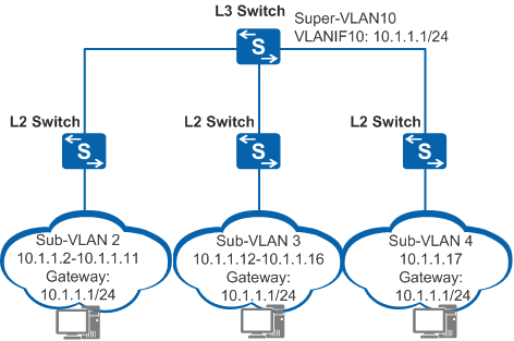
Sub-VLAN 2, sub-VLAN 3, and sub-VLAN 4 share a subnet (10.1.1.0/24). The subnet ID (10.1.1.0), default gateway address (10.1.1.1), and directed broadcast address of the subnet (10.1.1.255) cannot be used as host IP addresses. VLAN aggregation allows the switch to assign IP addresses to hosts in sub-VLANs according to the actual number of hosts. For example, if sub-VLAN 2 contains only 10 hosts, the switch allocates IP addresses 10.1.1.2 to 10.1.1.11 to sub-VLAN 2.
Communication Between Sub-VLANs
VLAN aggregation allows hosts in different sub-VLANs to communicate at Layer 2 but not at Layer 3.
To enable Layer 3 communication between hosts in different sub-VLANs, configure proxy ARP.

For details about proxy ARP, see Proxy ARP in "ARP Configuration" in the S2720, S5700, and S6700 V200R019C10 Configuration Guide - IP Services.
Figure 1 shows an example of using proxy ARP to implement Layer 3 communication between sub-VLANs. To allow Host_1 in sub-VLAN 2 to communicate with Host_2 in sub-VLAN 3, enable proxy ARP on the VLANIF interface of super-VLAN 10.
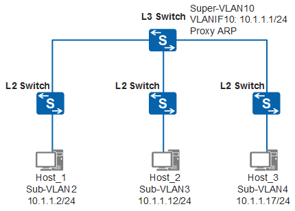
Host_1 communicates with Host_2 as follows (assume that the ARP table of Host_1 has no entry for Host_2):
- Host_1 compares the IP address of Host_2 with its IP address, and finds that both IP addresses are on the same network segment 10.1.1.0/24. However, the ARP table of Host_1 has no entry for Host_2.
- Host_1 broadcasts an ARP Request packet with the destination IP address of 10.1.1.12 to request the MAC address of Host_2.
- The Layer 3 switch (gateway) is enabled with proxy ARP between sub-VLANs. After receiving the ARP Request packet from Host_1, the Layer 3 switch searches its routing table for the destination IP address in the ARP Request packet. The Layer 3 switch finds a matched route in its routing table where the next-hop address is the directly connected network segment (10.1.1.0/24 of VLANIF 10). The Layer 3 switch then broadcasts an ARP Request packet to all sub-VLANs in super-VLAN 10, requesting the MAC address of Host_2.
- After receiving the ARP Request packet, Host_2 sends an ARP Reply packet.
- After receiving the ARP Reply packet, the Layer 3 switch encapsulates the ARP Reply packet with its MAC address and sends it to Host_1.
- Subsequent packets sent by Host_1 to Host_2 are first sent to the gateway. The gateway then forwards the packets across Layer 3.
The packets sent by Host_2 to Host_1 are processed in the same way as the packets sent by Host_1 to Host_2.
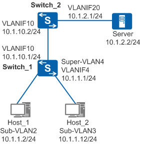
Layer 3 Communication Between Hosts in Sub-VLANs and on an External Network
In Figure 3, user hosts and servers reside on different network segments. Sub-VLANs 2 to 4 and VLAN 10 are configured on Switch_1, and VLAN 10 and VLAN 20 are configured on Switch_2.
- Host_1 compares the server's IP address (10.1.2.2) with its network segment 10.1.1.0/24 and finds that they are on different network segments. Host_1 then sends an ARP Request packet to its gateway to request the gateway's MAC address. The ARP Request packet carries an all-F (broadcast) destination MAC address and destination IP address 10.1.1.1.
- After receiving the ARP Request packet, Switch_1 searches its ARP table for a mapping between the super-VLAN and sub-VLANs. Switch_1 then sends an ARP Reply packet with the MAC address of VLANIF 4 (corresponding to super-VLAN 4) from an interface of sub-VLAN 2 to Host_1.
- After learning the gateway's MAC address, Host_1 sends a packet with the MAC address of VLANIF 4 (corresponding to super-VLAN 4) as the destination MAC address and a destination IP address of 10.1.2.2.
- After receiving the packet from Host_1, Switch_1 determines that the packet should be forwarded at Layer 3 according to the mapping between the super-VLAN and sub-VLANs and the destination MAC address. Switch_1 then searches its Layer 3 forwarding table for a matching entry, but none is found. Consequently, Switch_1 sends the packet to the CPU. The CPU searches its routing table and obtains the next-hop address of 10.1.10.2 and the outbound interface of VLANIF 10. Switch_1 determines the outbound interface according to the ARP entry and MAC address entry, and sends the packet to Switch_2.
- Switch_2 sends the packet to the server through Layer 3 forwarding.
- Switch_2 sends the response packet to Switch_1 through Layer 3 forwarding. At Switch_1, the destination MAC address contained in the packet is changed to the MAC address of VLANIF 10 on Switch_1.
- After receiving the packet, Switch_1 determines that the packet should be forwarded at Layer 3 according to the destination MAC address. Switch_1 then searches its Layer 3 forwarding table for a matching entry, but none is found. Consequently, Switch_1 sends the packet to the CPU. The CPU searches its routing table and obtains the next-hop address of 10.1.1.2 and the outbound interface of VLANIF 4. Switch_1 searches the mapping between the super-VLAN and sub-VLANs and determines that the packet should be sent to Host_1 from an interface in sub-VLAN 2 according to the ARP entry and MAC address entry.
- The response packet reaches Host_1.
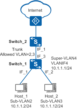
Layer 2 Communication Between Hosts in Sub-VLANs and Other Devices
- Sub-VLAN 2, sub-VLAN 3, and super-VLAN 4 are configured on Switch_1.
- IF_1 and IF_2 on Switch_1 are access interfaces.
- IF_3 is a trunk interface that allows both VLAN 2 and VLAN 3.
- The interface of Switch_2 connected to Switch_1 is a trunk interface and allows both VLAN 2 and VLAN 3.
For packets sent from Host_1 to Switch_1, a tag with VLAN 2 is added to the packets. This tag remains the same when Switch_1 sends these packets from its IF_3 interface even though sub-VLAN 2 belongs to super-VLAN 4.
Switch_1 does not send packets from VLAN 4. If Switch_1 receives packets from VLAN 4, it discards them because it has no physical interface corresponding to super-VLAN 4. In addition, IF_3 on Switch_1 does not allow packets from super-VLAN 4. In the preceding figure, only sub-VLAN 2 and sub-VLAN 3 are valid.
When VLAN aggregation is configured on Switch_1, communication between Switch_1 and other devices is similar to Layer 2 communication without super-VLAN.