Using a Dot1q Termination Sub-interface to Implement Inter-VLAN Communication
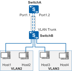
In Figure 1, SwitchA is a Layer 3 switch that supports sub-interface configuration and SwitchB is a Layer 2 switch. SwitchA connects to SwitchB through a Layer 3 Ethernet interface. User hosts are assigned to VLAN 2 and VLAN 3, and need to communicate with each other.
Perform the following operations to implement inter-VLAN communication:
Create sub-interfaces Port1.1 and Port1.2 on the Ethernet interface connecting SwitchA to SwitchB.
Configure Dot1q termination on Port1.1 and Port1.2 to remove VLAN tags in packets sent by SwitchB.
Assign IP addresses to Port1.1 and Port1.2.
Configure the IP addresses of Port1.1 and Port1.2 as the default gateway addresses for user hosts.
After the preceding operations are performed, user hosts in VLAN 2 and VLAN 3 can communicate at Layer 3. When a host in VLAN 2 sends packets to a host in VLAN 3, the process is as follows:
- Port1.1 removes the VLAN tag of the packets sent from VLAN 2 through SwitchB, and forwards the packets to Port1.2 at Layer 3.
- Before sending the packets out, Port1.2 adds VLAN 3 to the packets so that the packets can reach user hosts in VLAN 3.