Using a Dot1q Termination Sub-interface to Connect to a VPN
Using a Dot1q Termination Sub-interface to Connect to a PWE3/VLL/VPLS Network
In Figure 1, different branches of an enterprise are interconnected through a carrier's PWE3/VLL/VPLS network. PEs serve as edge devices of the carrier's PWE3/VLL/VPLS network and connect to branch networks through sub-interfaces, and packets sent from CEs to PEs carry single or double VLAN tags. User hosts in different branches need to communicate with each other.
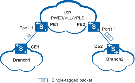
Dot1q termination and PWE3/VLL/VPLS are configured on sub-interfaces of PE1 and PE2. When a host in Branch 1 sends packets to a host in Branch 2, the process is as follows:
- PE1 checks the outer VLAN tag of data packets sent from CE1. If the VLAN tag is the same as that specified in the Dot1q termination configuration on Port1.1, PE1 encapsulates the packets with double MPLS labels into the packets and forwards the packets to the carrier's PWE3/VLL/VPLS network. VLAN tags are transparent to the carrier's PWE3/VLL/VPLS network.
- When receiving the packets, PE2 removes the double MPLS labels from the packets, and forwards the packets to CE2 according to the Dot1q termination configuration on Port1.1.
- CE2 forwards packets to user hosts.
Using a Dot1q Termination Sub-interface to Connect to an L3VPN
In Figure 2, different branches of an enterprise are interconnected through a carrier's MPLS L3VPN. PEs serve as edge devices of the carrier's MPLS L3VPN and connect to branch networks through sub-interfaces, and packets sent from CEs to PEs carry single or double VLAN tags. Hosts in different branches need to use the same services.
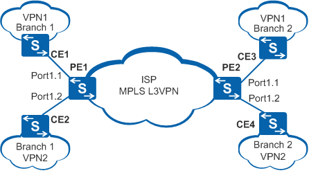
Dot1q termination and L3VPN are configured on sub-interfaces of PE1 and PE2. When a host in Branch 1 of VPN 1 sends packets to a host in Branch 2 of VPN 1, the process is as follows:
- According to the Dot1q termination configuration on Port1.1, PE1 removes the outer VLAN tag of the packets sent from CE1.
- PE1 binds the outer VLAN tag to the VPN instance VPN1, and forwards the packets to the L3VPN.
- After the packets reach PE2, PE2 determines that the packets are destined for CE3 based on the VPN instance.
- PE2 adds an outer VLAN tag to the packets according to the Dot1q termination configuration on Port1.1, and then forwards the packets to CE3.
- CE3 forwards the packets to the destination user host.