Example for Configuring Dot1q Termination Sub-interfaces to Implement Inter-VLAN Communication
Networking Requirements
An enterprise's departments are located on different network segments and use the same services such as Internet access and VoIP. To allow the departments in different VLANs to use the same service, inter-VLAN communication must be implemented.
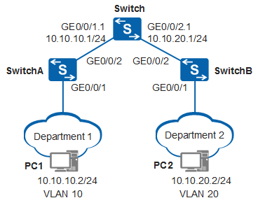
In the network example shown in Figure 1, both department 1 and department 2 located in different VLANs and network segments need to use the Internet access service, and users in department 1 and department 2 need to communicate with each other.
Configuration Roadmap
Configure the ID of the VLAN to which each interface belongs.
Configure Dot1q termination sub-interfaces.
Assign IP addresses to the sub-interfaces.

VLAN termination sub-interfaces cannot be created on a VCMP client.
Procedure
- Add the uplink interface of SwitchA to VLAN 10 in tagged mode and the user-side interface to VLAN 10 in untagged mode, and add the uplink interface of SwitchB to VLAN 20 in tagged mode and the user-side interface to VLAN 20 in untagged mode. Configure VLANs on interfaces of SwitchA and SwitchB.
<HUAWEI> system-view
[HUAWEI] sysname SwitchA
[SwitchA] vlan batch 10
[SwitchA] interface gigabitethernet0/0/1
[SwitchA-GigabitEthernet0/0/1] port link-type access
[SwitchA-GigabitEthernet0/0/1] port default vlan 10
[SwitchA-GigabitEthernet0/0/1] quit
[SwitchA] interface gigabitethernet0/0/2
[SwitchA-GigabitEthernet0/0/2] port link-type trunk
[SwitchA-GigabitEthernet0/0/2] port trunk allow-pass vlan 10
[SwitchA-GigabitEthernet0/0/2] quit
<HUAWEI> system-view
[HUAWEI] sysname SwitchB
[SwitchB] vlan batch 20
[SwitchB] interface gigabitethernet0/0/1
[SwitchB-GigabitEthernet0/0/1] port link-type access
[SwitchB-GigabitEthernet0/0/1] port default vlan 20
[SwitchB-GigabitEthernet0/0/1] quit
[SwitchB] interface gigabitethernet0/0/2
[SwitchB-GigabitEthernet0/0/2] port link-type trunk
[SwitchB-GigabitEthernet0/0/2] port trunk allow-pass vlan 20
[SwitchB-GigabitEthernet0/0/2] quit
- Configure the interface on the Switch connected to SwitchA.
# Create and configure the Ethernet sub-interface GE0/0/1.1.
<HUAWEI> system-view
[HUAWEI] sysname Switch
[Switch] vcmp role silent
[Switch] interface gigabitethernet0/0/1
[Switch-GigabitEthernet0/0/1] port link-type hybrid
[Switch-GigabitEthernet0/0/1] quit
[Switch] interface gigabitethernet0/0/1.1
[Switch-GigabitEthernet0/0/1.1] dot1q termination vid 10
[Switch-GigabitEthernet0/0/1.1] ip address 10.10.10.1 24
[Switch-GigabitEthernet0/0/1.1] arp broadcast enable
[Switch-GigabitEthernet0/0/1.1] quit
- Configure the interface on the Switch connected to SwitchB.
# Create and configure the Ethernet sub-interface GE0/0/2.1.
[Switch] interface gigabitethernet0/0/2
[Switch-GigabitEthernet0/0/2] port link-type hybrid
[Switch-GigabitEthernet0/0/2] quit
[Switch] interface gigabitethernet 0/0/2.1
[Switch-GigabitEthernet0/0/2.1] dot1q termination vid 20
[Switch-GigabitEthernet0/0/2.1] ip address 10.10.20.1 24
[Switch-GigabitEthernet0/0/2.1] arp broadcast enable
[Switch-GigabitEthernet0/0/2.1] quit
- Verify the configuration.
On PC1 in VLAN 10, set the default gateway address to 10.10.10.1/24, which is the IP address of GE0/0/1.1.
On PC2 in VLAN 20, set the default gateway address to 10.10.20.1/24, which is the IP address of GE0/0/2.1.
After the configuration is complete, PC1 in VLAN 10 and PC2 in VLAN 20 can communicate with each other.
Configuration Files
Switch configuration file
#
sysname Switch
#
vcmp role silent
#
interface GigabitEthernet0/0/1
 port link-type hybrid
#
interface GigabitEthernet0/0/1.1
 dot1q termination vid 10
 ip address 10.10.10.1 255.255.255.0
 arp broadcast enable
#
interface GigabitEthernet0/0/2
 port link-type hybrid
#
interface GigabitEthernet0/0/2.1
 dot1q termination vid 20
 ip address 10.10.20.1 255.255.255.0
 arp broadcast enable
#
return
SwitchA configuration file
#
sysname SwitchA
#
vlan batch 10
#
interface GigabitEthernet0/0/1
 port link-type access
 port default vlan 10
#
interface GigabitEthernet0/0/2
 port link-type trunk
 port trunk allow-pass vlan 10
#
return
SwitchB configuration file
#
sysname SwitchB
#
vlan batch 20
#
interface GigabitEthernet0/0/1
 port link-type access
 port default vlan 20
#
interface GigabitEthernet0/0/2
 port link-type trunk
 port trunk allow-pass vlan 20
#
return