Example for Configuring Dot1q Termination Sub-interfaces to Implement Inter-VLAN Communication Across Different Networks
Networking Requirements
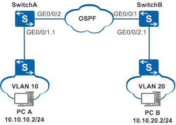
In the network example shown in Figure 1, SwitchA and SwitchB are connected to Layer 2 networks that VLAN 10 and VLAN 20 belong to. SwitchA communicates with SwitchB through a Layer 3 network where OSPF is running.
PCs of the two Layer 2 networks need to be isolated at Layer 2 and interwork at Layer 3.
Configuration Roadmap
Configure VLANs that interfaces belong to.
Assign IP addresses to VLANIF interfaces.
Set the encapsulation mode of sub-interfaces.
Configure VLANs allowed by sub-interfaces.
Assign IP addresses to the sub-interfaces.
Configure basic OSPF functions.

- The VLANs allowed by a sub-interface cannot be created in the system view.
VLAN termination sub-interfaces cannot be created on a VCMP client.
Procedure
- Configure SwitchA.
# Create a VLAN.
<HUAWEI> system-view
[HUAWEI] sysname SwitchA
[SwitchA] vlan batch 30
# Add an interface to the VLAN.
[SwitchA] interface gigabitethernet 0/0/2
[SwitchA-GigabitEthernet0/0/2] port link-type trunk
[SwitchA-GigabitEthernet0/0/2] port trunk allow-pass vlan 30
[SwitchA-GigabitEthernet0/0/2] quit
# Assign an IP address to a VLANIF interface.
[SwitchA] interface vlanif 30
[SwitchA-Vlanif30] ip address 10.10.30.1 24
[SwitchA-Vlanif30] quit
# Create and configure GE0/0/1.1.
[SwitchA] vcmp role silent
[SwitchA] interface gigabitethernet0/0/1
[SwitchA-GigabitEthernet0/0/1] port link-type hybrid
[SwitchA-GigabitEthernet0/0/1] quit
[SwitchA] interface gigabitethernet 0/0/1.1
[SwitchA-GigabitEthernet0/0/1.1] dot1q termination vid 10
[SwitchA-GigabitEthernet0/0/1.1] ip address 10.10.10.1 24
[SwitchA-GigabitEthernet0/0/1.1] arp broadcast enable
[SwitchA-GigabitEthernet0/0/1.1] quit
# Configure basic OSPF functions.
[SwitchA] router id 1.1.1.1
[SwitchA] ospf
[SwitchA-ospf-1] area 0
[SwitchA-ospf-1-area-0.0.0.0] network 10.10.10.0 0.0.0.255
[SwitchA-ospf-1-area-0.0.0.0] network 10.10.30.0 0.0.0.255
[SwitchA-ospf-1-area-0.0.0.0] return
- Configure SwitchB.
# Create a VLAN.
<HUAWEI> system-view
[HUAWEI] sysname SwitchB
[SwitchB] vlan batch 30
# Add an interface to the VLAN.
[SwitchB] interface gigabitethernet 0/0/1
[SwitchB-GigabitEthernet0/0/1] port link-type trunk
[SwitchB-GigabitEthernet0/0/1] port trunk allow-pass vlan 30
[SwitchB-GigabitEthernet0/0/1] quit
# Assign an IP address to a VLANIF interface.
[SwitchB] interface vlanif 30
[SwitchB-Vlanif30] ip address 10.10.30.2 24
[SwitchB-Vlanif30] quit
# Create and configure GE0/0/2.1.
[SwitchB] vcmp role silent
[SwitchB] interface gigabitethernet0/0/2
[SwitchB-GigabitEthernet0/0/2] port link-type hybrid
[SwitchB-GigabitEthernet0/0/2] quit
[SwitchB] interface gigabitethernet 0/0/2.1
[SwitchB-GigabitEthernet0/0/2.1] dot1q termination vid 20
[SwitchB-GigabitEthernet0/0/2.1] ip address 10.10.20.1 24
[SwitchB-GigabitEthernet0/0/2.1] arp broadcast enable
[SwitchB-GigabitEthernet0/0/2.1] quit
# Configure basic OSPF functions.
[SwitchB] router id 2.2.2.2
[SwitchB] ospf
[SwitchB-ospf-1] area 0
[SwitchB-ospf-1-area-0.0.0.0] network 10.10.20.0 0.0.0.255
[SwitchB-ospf-1-area-0.0.0.0] network 10.10.30.0 0.0.0.255
[SwitchB-ospf-1-area-0.0.0.0] return
- Verify the configuration.
On the PCs residing on the Layer 2 network connected to SwitchA, set the default gateway address to 10.10.10.1/24, which is the IP address of GE0/0/1.1. The switch connected to SwitchA allows VLAN 10.
On the PCs residing on the Layer 2 network connected to SwitchB, set the default gateway address to 10.10.20.1/24, which is the IP address of GE0/0/2.1. The switch connected to SwitchA allows VLAN 20.
After the configuration is complete, PCs on the two Layer 2 networks are isolated at Layer 2 and interwork at Layer 3.
Configuration Files
SwitchA configuration file
#
sysname SwitchA
#
router id 1.1.1.1
#
vcmp role silent
#
vlan batch 30
#
interface Vlanif30
 ip address 10.10.30.1 255.255.255.0
#
interface GigabitEthernet0/0/1  port link-type hybrid #
interface GigabitEthernet0/0/1.1
 dot1q termination vid 10
 ip address 10.10.10.1 255.255.255.0
 arp broadcast enable
#
interface GigabitEthernet0/0/2
 port link-type trunk
 port trunk allow-pass vlan 30
#
ospf 1
 area 0.0.0.0
  network 10.10.10.0 0.0.0.255
  network 10.10.30.0 0.0.0.255
#
return
SwitchB configuration file
#
sysname SwitchB
#
router id 2.2.2.2
#
vcmp role silent
#
vlan batch 30
#
interface Vlanif30
 ip address 10.10.30.2 255.255.255.0
#
interface GigabitEthernet0/0/1
 port link-type trunk
 port trunk allow-pass vlan 30
#
interface GigabitEthernet0/0/2  port link-type hybrid #
interface GigabitEthernet0/0/2.1
 dot1q termination vid 20
 ip address 10.10.20.1 255.255.255.0
 arp broadcast enable
#
ospf 1
 area 0.0.0.0
  network 10.10.20.0 0.0.0.255
  network 10.10.30.0 0.0.0.255
#
return