Inter-VLAN Communication
VLAN isolates broadcast domains, meaning broadcast packets are only forwarded in the same VLAN. That is, hosts in different VLANs cannot communicate at Layer 2. In real-world applications, hosts in different VLANs often need to communicate, which requires inter-VLAN communication.
Inter-VLAN communication goes through the same three phases as intra-VLAN communication described in Intra-VLAN Communication: packet transmission from the source host, Ethernet switching in a switch, and adding and removing VLAN tags during the exchange between devices. Users in different VLANs can communicate with each other using the Layer 3 routing or VLAN translation technology.
Inter-VLAN Communication Technologies
VLANIF interface
A VLANIF interface is a Layer 3 logical interface that can be used to implement inter-VLAN Layer 3 communication.
It is simple to configure a VLANIF interface, so this is the most commonly used method for inter-VLAN communication. Each VLAN corresponds to a VLANIF interface. After an IP address is configured for a VLANIF interface, the VLANIF interface is used as the gateway of the VLAN and forwards packets across network segments at Layer 3. However, a VLANIF interface needs to be configured for each VLAN and each VLANIF interface requires an IP address, wasting IP addresses.
In some scenarios, you need to configure multiple IP addresses for a VLANIF interface. For example, a switch connects to a physical network only through one interface but hosts on the physical network belong to different network segments. To enable the switch to communicate with all hosts on the physical network, you need to configure a primary IP address and multiple secondary IP addresses for this interface.
Dot1q termination sub-interface
A sub-interface is also a Layer 3 logical interface that can be used to implement inter-VLAN Layer 3 communication.
A Dot1q termination sub-interface applies to scenarios where a Layer 3 Ethernet interface connects to multiple VLANs. In such a scenario, data flows from different VLANs preempt bandwidth of the primary Ethernet interface; therefore, the primary Ethernet interface may become a bottleneck when the network is busy.
For details about the Dot1q termination sub-interface, see VLAN Termination Configuration.
VLANIF interfaces require that users in VLANs be located on different network segments. (When hosts are located on the same network segment, a host encapsulates the destination host's MAC address in packets. The device determines that packets should be forwarded at Layer 2. Layer 2 switching is performed only in the same VLAN, and broadcast packets cannot reach different VLANs. In this case, the device cannot obtain the destination host's MAC addresses and therefore cannot forward packets to the destination host.) On a network, VLAN aggregation can allow hosts on the same network segment in different VLANs to communicate.
VLAN aggregation, also known as super-VLAN, associates a super-VLAN with multiple sub-VLANs. The sub-VLANs share the IP address of the super-VLAN as the gateway IP address to implement Layer 3 communication with an external network. Proxy ARP can be enabled between sub-VLANs to implement Layer 3 communication between sub-VLANs. VLAN aggregation conserves IP addresses in inter-VLAN Layer 3 communication.
VLAN aggregation applies to scenarios where multiple VLANs share a gateway. For details about VLAN aggregation, see VLAN Aggregation Configuration.
Inter-VLAN Communication Through the Same Switch
As shown in Figure 1, Host_1 (source host) and Host_2 (destination host) connect to the same Layer 3 switch, are located on different network segments, and belong to VLAN 2 and VLAN 3, respectively. After VLANIF 2 and VLANIF 3 are created on the switch and allocated IP addresses, the default gateway addresses of the hosts are set to IP addresses of the VLANIF interfaces.
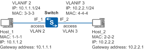
When Host_1 sends a packet to Host_2, the packet is transmitted as follows (assuming that no forwarding entry exists on the switch):
- Host_1 determines that the destination IP address is on a different network segment from its own IP address, and therefore sends an ARP Request packet to request the gateway MAC address. The ARP Request packet carries the destination IP address of 10.1.1.1 (gateway's IP address) and all-F destination MAC address.
- When the ARP Request packet reaches IF_1 on the Switch, the Switch tags the packet with VLAN 2 (PVID of IF_1). The Switch then adds the mapping between the source MAC address, VLAN ID, and interface (1-1-1, 2, IF_1) to its MAC address table.
- The Switch detects that the packet is an ARP Request packet and the destination IP address is the IP address of VLANIF 2. The Switch then encapsulates VLANIF 2's MAC address of 3-3-3 into the ARP Reply packet and removes the tag with VLAN 2 from the packet before sending it from IF_1. In addition, the Switch adds the mapping between the IP address and MAC address of Host_1 in its ARP table.
- After receiving the ARP Reply packet from the Switch, Host_1 adds the mapping between the IP address and MAC address of VLANIF 2 on the Switch to its ARP table and sends a packet to the Switch. The packet carries the destination MAC address of 3-3-3 and destination IP address of 10.2.2.2 (Host_2's IP address).
- After the packet reaches IF_1 on the Switch, the Switch tags the packet with VLAN 2.
- The Switch updates its MAC address table based on the source MAC address, VLAN ID, and inbound interface of the packet, and compares the destination MAC address of the packet with the MAC address of VLANIF 2. If they are the same, the Switch determines that the packet should be forwarded at Layer 3 and searches for a Layer 3 forwarding entry based on the destination IP address. If no entry is found, the Switch sends the packet to the CPU. The CPU then searches for a routing entry to forward the packet.
- The CPU looks up the routing table based on the destination IP address of the packet and detects that the destination IP address matches a directly connected network segment (network segment of VLANIF 3). The CPU continues to look up its ARP table but finds no matching ARP entry. Therefore, the Switch broadcasts an ARP Request packet with the destination address of 10.2.2.2 to all interfaces in VLAN 3. Before sending the ARP Request packet from IF_2, the Switch removes the tag with VLAN 2 from the packet.
- After receiving the ARP Request packet, Host_2 detects that the IP address is its own IP address and sends an ARP Reply packet with its own MAC address. Additionally, Host_2 adds the mapping between the MAC address and IP address of VLANIF 3 to its ARP table.
- After IF_2 on the Switch receives the ARP Reply packet, IF_2 tags the packet with VLAN 3 to the packet and adds the mapping between the MAC address and IP address of Host_2 to its ARP table. Before forwarding the packet from Host_1 to Host_2, the Switch removes the tag with VLAN 3 from the packet. The Switch also adds the binding of Host_2's IP address, MAC address, VLAN ID, and outbound interface in its Layer 3 forwarding table.
In this way, the packet sent from Host_1 then reaches Host_2. The packet transmission process from Host_2 to Host_1 is similar. Subsequent packets between Host_1 and Host_2 are first sent to the gateway (Switch), and the Switch forwards the packets at Layer 3 based on its Layer 3 forwarding table.
Inter-VLAN Communication Through Multiple Switches
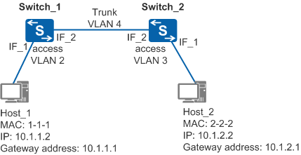
When hosts in different VLANs connect to multiple Layer 3 switches, you need to configure static routes or a dynamic routing protocol in addition to VLANIF interface addresses. This is because IP addresses of VLANIF interfaces can only be used to generate direct routes.
As shown in Figure 2, Host_1 (source host) and Host_2 (destination host) are located on different network segments, connect to Layer 3 switches Switch_1 and Switch_2, and belong to VLAN 2 and VLAN 3, respectively. On Switch_1, VLANIF 2 and VLANIF 4 are created and allocated IP addresses of 10.1.1.1 and 10.1.4.1. On Switch_2, VLANIF 3 and VLANIF 4 are created and allocated IP addresses of 10.1.2.1 and 10.1.4.2, respectively. Static routes are configured on Switch_1 and Switch_2. On Switch_1, the destination network segment in the static route is 10.1.2.0/24 and the next hop address is 10.1.4.2. On Switch_2, the destination network segment in the static route is 10.1.1.0/24 and the next hop address is 10.1.4.1.
When Host_1 sends a packet to Host_2, the packet is transmitted as follows (assuming that no forwarding entry exists on Switch_1 and Switch_2):
- The first six steps are the same as steps 1 to 6 in Inter-VLAN Communication Through the Same Switch and are not repeated here. After the steps are complete, Switch_1 sends the packet to its CPU and the CPU looks up the routing table.
- The CPU of Switch_1 searches for the routing table based on the destination IP address of 10.1.2.2 in the routing table and finds a static route. In the static route, the destination network segment is 10.1.2.0/24 and the next hop address is 10.1.4.2. The CPU continues to look up its ARP table but finds no matching ARP entry. Therefore, Switch_1 broadcasts an ARP Request packet with the destination address of 10.1.4.2 to all interfaces in VLAN 4. IF_2 on Switch_1 transparently transmits the ARP Request packet to IF_2 on Switch_2 without removing the tag from the packet.
- After the ARP Request packet reaches Switch_2, Switch_2 finds that the destination IP address of the ARP Request packet is the IP address of VLANIF 4. Switch_2 then sends an ARP Reply packet with the MAC address of VLANIF 4 to Switch_1.
- IF_2 on Switch_2 transparently transmits the ARP Reply packet to Switch_1. After Switch_1 receives the ARP Reply packet, it adds the mapping between the MAC address and IP address of VLANIF4 to its ARP table.
- Before forwarding the packet of Host_1 to Switch_2, Switch_1 changes the destination MAC address of the packet to the MAC address of VLANIF 4 on Switch_2 and the source MAC address to the MAC address of its local VLANIF 4. In addition, Switch_1 records the forwarding entry (10.1.2.0/24, next hop IP address, VLAN, and outbound interface) in its Layer 3 forwarding table. Similarly, the packet is transparently transmitted to IF_2 on Switch_2.
- After Switch_2 receives packets of Host_1 forwarded by Switch_1, the same steps as steps 6 to 9 in Inter-VLAN Communication Through the Same Switch are performed. In addition, Switch_2 records the forwarding entry (Host_2's IP address, MAC address, VLAN, and outbound interface) in its Layer 3 forwarding table.