Intra-VLAN Communication
Packets transmitted between users in a VLAN go through three phases:
Packet transmission from the source host
Before sending a frame, the source host compares its IP address with the destination IP address. If the two IP addresses are on the same network segment, the source host obtains the MAC address of the destination host and fills the destination MAC address of the frame with the obtained MAC address. If the two IP addresses are on different network segments, the frame needs to be forwarded by the gateway. The source host obtains the gateway's MAC address, and uses it as the destination MAC address to send the frame to the gateway.
Ethernet switching in a switch
The following describes how the switch determines whether to forward a received frame at Layer 2 or Layer 3 based on the information in the destination MAC address, VLAN ID, and Layer 3 forwarding bit:- If the destination MAC address and VLAN ID of the frame match a MAC address entry of the switch and the Layer 3 forwarding bit is set, the switch searches for a Layer 3 forwarding entry based on the destination IP address. If no entry is found, the switch sends the frame to the CPU. The CPU then searches for a route to forward the frame at Layer 3.
- If the destination MAC address and VLAN ID of the frame match a MAC address entry but the Layer 3 forwarding bit is not set, the switch directly forwards the frame from the outbound interface specified in the matching MAC address entry.
- If the destination MAC address and VLAN ID of the frame do not match any MAC address entry, the switch broadcasts the frame to all the interfaces allowing the VLAN specified in the VID to obtain the MAC address of the destination host.
For details about Layer 2 and Layer 3 switching, see Layer 2 Switching and Layer 3 Switching.
Adding and removing VLAN tags during the exchange between devices (for example, between a switch and a user host, another switch, or another network device)
The switch needs to add or remove VLAN tags according to the interface setting to communicate with other network devices. For details on how VLAN tags are added and removed on different types of interfaces, see Adding and Removing VLAN Tags.
After VLANs are assigned, broadcast packets are forwarded at Layer 2 in the same VLAN. That is, users in the same VLAN can directly communicate at Layer 2. There are two intra-VLAN communication scenarios depending on whether hosts in the same VLAN connect to the same or multiple switches.
Intra-VLAN Communication Through the Same Switch
As shown in Figure 1, Host_1 and Host_2 connect to the same switch, belong to VLAN 2, and are located on the same network segment. The interfaces connected to Host_1 and Host_2 are access interfaces.
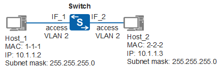
When Host_1 sends a packet to Host_2, the packet is transmitted as follows (assuming that no forwarding entry exists on the switch):
- Host_1 determines that the destination IP address is on the same network segment as its IP address, and therefore broadcasts an ARP Request packet to obtain the MAC address of Host_2. The ARP Request packet carries the all-F destination MAC address and destination IP address of 10.1.1.3 (Host_2's IP address).
- When the packet reaches IF_1 on the Switch, the Switch detects that the ARP Request packet is untagged and adds VLAN 2 (PVID of IF_1) to the packet. The Switch then adds the mapping between the source MAC address, VLAN ID, and interface (1-1-1, 2, IF_1) to its MAC address table.
- The Switch does not find a MAC address entry matching the destination MAC address and VLAN ID of the ARP Request packet, so it broadcasts the ARP Request packet to all interfaces that allow VLAN 2 (IF_2 in this example) except to the interface that it received the packet on.
- Before sending the ARP Request packet, IF_2 on the Switch removes the tag with VLAN 2 from the packet.
- Host_2 receives the ARP Request packet and records the mapping between the MAC address and IP address of Host_1 in the ARP table. Then Host_2 compares the destination IP address with its own IP address. If they are the same, Host_2 sends an ARP Reply packet. The ARP Reply packet carries Host_2's MAC address of 2-2-2 and Host_1's IP address of 10.1.1.2 as the destination IP address.
- After receiving the ARP Reply packet, IF_2 on the Switch tags the packet with VLAN 2.
- The Switch adds the mapping between the source MAC address, VLAN ID, and interface (2-2-2, 2, IF_2) to its MAC address table, and then searches for an entry in its MAC address table based on the destination MAC address and VLAN ID (1-1-1, 2). The entry is found because the mapping has been recorded (see step 5). The Switch forwards the ARP Reply packet to IF_1.
- Before forwarding the ARP Reply packet to IF_1, the Switch removes the tag with VLAN 2 from the packet.
- Host_1 receives the ARP Reply packet and records the mapping between the MAC address and IP address of Host_2 in the ARP table.
Host_1 and Host_2 have now learned the MAC address of each other. In subsequent communication, they can fill the destination MAC address fields of packets with each other's MAC address.
In the preceding networking, if hosts in the same VLAN are on different network segments, they encapsulate the gateway's MAC address into packets. If the Switch is a Layer 2 switch, hosts cannot communicate. If the Switch is a Layer 3 switch, hosts can communicate through VLANIF interfaces (with primary and secondary IP addresses configured). The principles are similar to those in Inter-VLAN Communication Through the Same Switch, and are not described in detail here.
Intra-VLAN Communication Through Multiple Switches
As shown in Figure 2, Host_1 and Host_2 connect to different switches, belong to VLAN 2, and are located on the same network segment. The switches are connected using a trunk link over which frames can be identified and sent between switches.
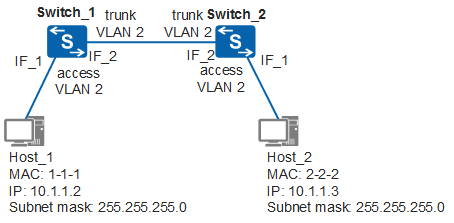
- The first two steps are the same as steps 1 and 2 in Intra-VLAN Communication Through the Same Switch and are not repeated here. After the two steps are complete, Host_1 broadcasts the ARP Request packet to IF_2 on Switch_1.
- IF_2 on Switch_1 transparently transmits the ARP Request packet to IF_2 on Switch_2 without removing the tag of the packet (also known as transparent transmission), because the VLAN ID of the packet is different from the PVID of IF_2 on Switch_1.
- After receiving the ARP Request packet, IF_2 on Switch_2 determines that VLAN 2 is an allowed VLAN and accepts the packet.
- The next four steps are the same as steps 3 to 6 in Intra-VLAN Communication Through the Same Switch and are not repeated here. After these steps are complete, Switch_2 forwards the ARP Reply packet of Host_2 to IF_2. IF_2 on Switch_2 transparently transmits the ARP Reply packet to IF_2 on Switch_1, because IF_2 is a trunk interface and its PVID is different from the VLAN ID of the packet.
- After receiving the ARP Reply packet, IF_2 on Switch_1 determines that VLAN 2 is an allowed VLAN and accepts the packet. Subsequent steps are the same as steps 7 to 9 in Intra-VLAN Communication Through the Same Switch and are not repeated here.
In addition to transmitting frames from multiple VLANs, a trunk link can transparently transmit frames.
In the preceding networking, if hosts in the same VLAN are on different network segments and Switch_1 or Switch_2 is a Layer 2 switch, hosts cannot communicate. If Switch_1 or Switch_2 is a Layer 3 switch, hosts can communicate through VLANIF interfaces. The principles are similar to those in Inter-VLAN Communication Through the Same Switch, and are not mentioned here.