Example for Configuring VLANIF Interfaces to Implement Intra-VLAN Communication
Networking Requirements
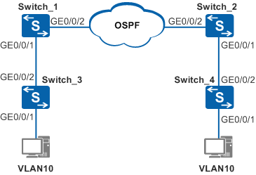
In Figure 1, Switch_1 and Switch_2 are connected to Layer 2 networks that VLAN 10 belongs to. Switch_1 communicates with Switch_2 through a Layer 3 network with OSPF enabled.
PCs of the two Layer 2 networks need to be isolated at Layer 2 and interwork at Layer 3.
Configuration Roadmap
Add interfaces to VLANs and configure the interfaces to allow the VLANs.
Configure IP addresses for VLANIF interfaces to implement Layer 3 connectivity.
Configure basic OSPF functions to implement Layer 3 interworking.
Procedure
- Configure Switch_1.
# Create VLAN 10 and VLAN 30.
<HUAWEI> system-view
[HUAWEI] sysname Switch_1
[Switch_1] vlan batch 10 30
# Add GE0/0/1 to VLAN 10 and GE0/0/2 to VLAN 30.
[Switch_1] interface gigabitethernet 0/0/1
[Switch_1-GigabitEthernet0/0/1] port link-type trunk
[Switch_1-GigabitEthernet0/0/1] port trunk allow-pass vlan 10
[Switch_1-GigabitEthernet0/0/1] quit
[Switch_1] interface gigabitethernet 0/0/2
[Switch_1-GigabitEthernet0/0/2] port link-type trunk
[Switch_1-GigabitEthernet0/0/2] port trunk allow-pass vlan 30
[Switch_1-GigabitEthernet0/0/2] quit
# Configure IP addresses of 10.10.10.1/24 for VLANIF 10 and 10.10.30.1/24 for VLANIF 30.
[Switch_1] interface vlanif 10
[Switch_1-Vlanif10] ip address 10.10.10.1 24
[Switch_1-Vlanif10] quit
[Switch_1] interface vlanif 30
[Switch_1-Vlanif30] ip address 10.10.30.1 24
[Switch_1-Vlanif30] quit
# Configure basic OSPF functions.
[Switch_1] router id 1.1.1.1
[Switch_1] ospf
[Switch_1-ospf-1] area 0
[Switch_1-ospf-1-area-0.0.0.0] network 10.10.10.0 0.0.0.255
[Switch_1-ospf-1-area-0.0.0.0] network 10.10.30.0 0.0.0.255
[Switch_1-ospf-1-area-0.0.0.0] quit
- Configure Switch_2.
# Create VLAN 10 and VLAN 30.
<HUAWEI> system-view
[HUAWEI] sysname Switch_2
[Switch_2] vlan batch 10 30
# Add GE0/0/1 to VLAN 10 and GE0/0/2 to VLAN 30.
[Switch_2] interface gigabitethernet 0/0/1
[Switch_2-GigabitEthernet0/0/1] port link-type trunk
[Switch_2-GigabitEthernet0/0/1] port trunk allow-pass vlan 10
[Switch_2-GigabitEthernet0/0/1] quit
[Switch_2] interface gigabitethernet 0/0/2
[Switch_2-GigabitEthernet0/0/2] port link-type trunk
[Switch_2-GigabitEthernet0/0/2] port trunk allow-pass vlan 30
[Switch_2-GigabitEthernet0/0/2] quit
# Configure VLANIF 10 and VLANIF 30 with IP addresses 10.10.20.1/24 and 10.10.30.2/24 respectively.
[Switch_2] interface vlanif 10
[Switch_2-Vlanif10] ip address 10.10.20.1 24
[Switch_2-Vlanif10] quit
[Switch_2] interface vlanif 30
[Switch_2-Vlanif30] ip address 10.10.30.2 24
[Switch_2-Vlanif30] quit
# Configure basic OSPF functions.
[Switch_2] router id 2.2.2.2
[Switch_2] ospf
[Switch_2-ospf-1] area 0
[Switch_2-ospf-1-area-0.0.0.0] network 10.10.20.0 0.0.0.255
[Switch_2-ospf-1-area-0.0.0.0] network 10.10.30.0 0.0.0.255
[Switch_2-ospf-1-area-0.0.0.0] quit
- Configure Switch_3.
# Create VLAN 10, add GE0/0/1 to VLAN 10 in untagged mode and GE0/0/2 to VLAN 10 in tagged mode. The configuration of Switch_4 is the same as that of Switch_3.
<HUAWEI> system-view
[HUAWEI] sysname Switch_3
[Switch_3] vlan batch 10
[Switch_3] interface gigabitethernet 0/0/1
[Switch_3-GigabitEthernet0/0/1] port link-type access
[Switch_3-GigabitEthernet0/0/1] port default vlan 10
[Switch_3-GigabitEthernet0/0/1] quit
[Switch_3] interface gigabitethernet 0/0/2
[Switch_3-GigabitEthernet0/0/2] port link-type trunk
[Switch_3-GigabitEthernet0/0/2] port trunk allow-pass vlan 10
[Switch_3-GigabitEthernet0/0/2] quit
- Verify the configuration.
On the PC of the Layer 2 network connected to Switch_1, set the default gateway address to 10.10.10.1/24 (the IP address of VLANIF10).
On the PC of the Layer 2 network connected to Switch_2, set the default gateway address to 10.10.20.1/24 (the IP address of VLANIF10).
After the configuration is complete, PCs on the two Layer 2 networks are isolated at Layer 2 and interwork at Layer 3.
Configuration Files
Switch_1 configuration file
#
sysname Switch_1
#
router id 1.1.1.1
#
vlan batch 10 30
#
interface Vlanif10
 ip address 10.10.10.1 255.255.255.0
#
interface Vlanif30
 ip address 10.10.30.1 255.255.255.0
#
interface GigabitEthernet0/0/1
 port link-type trunk
 port trunk allow-pass vlan 10
#
interface GigabitEthernet0/0/2
 port link-type trunk
 port trunk allow-pass vlan 30
#
ospf 1
 area 0.0.0.0
  network 10.10.10.0 0.0.0.255
  network 10.10.30.0 0.0.0.255
#
return
Switch_2 configuration file
#
sysname Switch_2
#
router id 2.2.2.2
#
vlan batch 10 30
#
interface Vlanif10
 ip address 10.10.20.1 255.255.255.0
#
interface Vlanif30
 ip address 10.10.30.2 255.255.255.0
#
interface GigabitEthernet0/0/1
 port link-type trunk
 port trunk allow-pass vlan 10
#
interface GigabitEthernet0/0/2
 port link-type trunk
 port trunk allow-pass vlan 30
#
ospf 1
 area 0.0.0.0
  network 10.10.20.0 0.0.0.255
  network 10.10.30.0 0.0.0.255
#
return
Switch_3 configuration file
#
sysname Switch_3
#
vlan batch 10
#
interface GigabitEthernet0/0/1
 port link-type access
 port default vlan 10
#
interface GigabitEthernet0/0/2
 port link-type trunk
 port trunk allow-pass vlan 10
#
return
Switch_4 configuration file
#
sysname Switch_4
#
vlan batch 10
#
interface GigabitEthernet0/0/1
 port link-type access
 port default vlan 10
#
interface GigabitEthernet0/0/2
 port link-type trunk
 port trunk allow-pass vlan 10
#
return