Example for Configuring VLANIF Interfaces to Implement Communication of Hosts on Different Network Segments in the Same VLAN
Networking Requirements
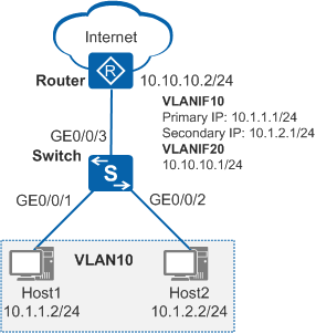
On the enterprise network shown in Figure 1, hosts in the same VLAN belong to network segments of 10.1.1.1/24 and 10.1.2.1/24. Hosts on the two network segments need to access the Internet through the Switch and still communicate.
Configuration Roadmap
If only one IP address is configured for the VLANIF interface on the Switch, only hosts on one network segment can access the Internet through the Switch. To enable all hosts on the LAN to access the Internet through the Switch, configure a secondary IP address for the VLANIF interface. To enable hosts on the two network segments to communicate, the hosts on the two network segments need to use the primary and secondary IP addresses of the VLANIF interface as default gateway addresses.
The configuration roadmap is as follows:
Create VLANs and add interfaces to the VLANs.
Configure VLANIF interfaces and assign IP addresses to them so that hosts on the two network segments can communicate.
Configure a routing protocol so that hosts can access the Internet through the Switch.
Procedure
- Create VLANs and add interfaces to the VLANs.
# Create VLAN 10 and VLAN 20.
<HUAWEI> system-view
[HUAWEI] sysname Switch
[Switch] vlan batch 10 20
# Add GE0/0/1 and GE0/0/2 to VLAN 10 and GE0/0/3 to VLAN 20.
[Switch] interface gigabitethernet 0/0/1
[Switch-GigabitEthernet0/0/1] port link-type access
[Switch-GigabitEthernet0/0/1] port default vlan 10
[Switch-GigabitEthernet0/0/1] quit
[Switch] interface gigabitethernet 0/0/2
[Switch-GigabitEthernet0/0/2] port link-type access
[Switch-GigabitEthernet0/0/2] port default vlan 10
[Switch-GigabitEthernet0/0/2] quit
[Switch] interface gigabitethernet 0/0/3
[Switch-GigabitEthernet0/0/3] port link-type trunk
[Switch-GigabitEthernet0/0/3] port trunk allow-pass vlan 20
[Switch-GigabitEthernet0/0/3] quit
- Configure VLANIF interfaces.
# Create VLANIF 10 and configure a primary IP address of 10.1.1.1/24 and a secondary IP address of 10.1.2.1/24 for VLANIF 10. Create VLANIF 20 and configure an IP address of 10.10.10.1/24 for VLANIF 20.
[Switch] interface vlanif 10
[Switch-Vlanif10] ip address 10.1.1.1 24
[Switch-Vlanif10] ip address 10.1.2.1 24 sub
[Switch-Vlanif10] quit
[Switch] interface vlanif 20
[Switch-Vlanif20] ip address 10.10.10.1 24
[Switch-Vlanif20] quit
- Configure a routing protocol.
# Configure basic OSPF functions and then configure OSPF to advertise both the network segments of hosts and the network segment between the Switch and router.
[Switch] ospf
[Switch-ospf-1] area 0
[Switch-ospf-1-area-0.0.0.0] network 10.1.1.0 0.0.0.255
[Switch-ospf-1-area-0.0.0.0] network 10.1.2.0 0.0.0.255
[Switch-ospf-1-area-0.0.0.0] network 10.10.10.0 0.0.0.255
[Switch-ospf-1-area-0.0.0.0] quit
[Switch-ospf-1] quit
 Perform the following configurations on the router:
- Add the interface connected to the Switch to VLAN 20 in tagged mode. Specify an IP address for VLANIF 20 on the same network segment as 10.10.10.1.
- Configure basic OSPF functions and configure OSPF to advertise the network segment between the Switch and router.
For details, see the router documentation.
- Verify the configuration.
Configure Host1 with an IP address of 10.1.1.2 and a default gateway address of 10.1.1.1/24 (primary IP address of VLANIF 10).
Configure Host2 with an IP address of 10.1.2.2 and a default gateway address of 10.1.2.1/24 (secondary IP address of VLANIF 10).
After the configuration is complete, Host1 and Host2 can ping each other. They can also access the Internet though the IP address of the router interface connected to the Switch (10.10.10.2/24).
Configuration Files
Switch configuration file
#
sysname Switch
#
vlan batch 10 20
#
interface Vlanif10
 ip address 10.1.1.1 255.255.255.0
 ip address 10.1.2.1 255.255.255.0 sub
#
interface Vlanif20
 ip address 10.10.10.1 255.255.255.0
#
interface GigabitEthernet0/0/1
 port link-type access
 port default vlan 10
#
interface GigabitEthernet0/0/2
 port link-type access
 port default vlan 10
#
interface GigabitEthernet0/0/3
 port link-type trunk
 port trunk allow-pass vlan 20
#
ospf 1
 area 0.0.0.0
  network 10.1.1.0 0.0.0.255
  network 10.1.2.0 0.0.0.255
  network 10.10.10.0 0.0.0.255
#
return