Example for Configuring a Traffic Policy to Implement Inter-VLAN Layer 3 Isolation
Networking Requirements
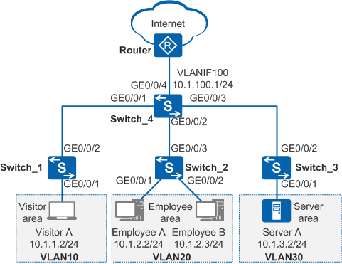
In Figure 1, a company assigns visitors, employees, and servers to VLAN 10, VLAN 20, and VLAN 30 respectively to ensure communication security. The requirements are as follows:
- Employees, visitors, and servers can access the Internet.
- Visitors can access only the Internet, and cannot communicate with any other VLANs.
- Employee A can access all resources in the server area, but other employees can access only port 21 (FTP service) of server A.
Configuration Roadmap
Create VLANs and add interfaces to the VLANs to implement Layer 2 isolation of visitors, employees, and servers.
Configure VLANIF interfaces and assign IP addresses to them to implement Layer 3 connectivity between employees, servers, and visitors.
Configure a routing protocol so that visitors, employees, and servers can access the Internet through Switch.
Configure and apply a traffic policy so that employee A can access all resources in the server area, other employees can access only port 21 (FTP service) of server A, only employees can access servers, and visitors can access only the Internet.
Procedure
- Create VLANs and add interfaces to the VLANs to implement Layer 2 isolation of visitors, employees, and servers.
# Create VLAN 10 on Switch_1, add GE0/0/1 to VLAN 10 in untagged mode and GE0/0/2 to VLAN 10 in tagged mode. The configurations of Switch_2 and Switch_3 are the same as that of Switch_1.
<HUAWEI> system-view
[HUAWEI] sysname Switch_1
[Switch_1] vlan batch 10
[Switch_1] interface gigabitethernet 0/0/1
[Switch_1-GigabitEthernet0/0/1] port link-type access
[Switch_1-GigabitEthernet0/0/1] port default vlan 10
[Switch_1-GigabitEthernet0/0/1] quit
[Switch_1] interface gigabitethernet 0/0/2
[Switch_1-GigabitEthernet0/0/2] port link-type trunk
[Switch_1-GigabitEthernet0/0/2] port trunk allow-pass vlan 10
[Switch_1-GigabitEthernet0/0/2] quit
# Create VLAN 10, VLAN 20, VLAN 30, and VLAN 100 on Switch_4, and add GE0/0/1-GE0/0/4 to VLAN 10, VLAN 20, VLAN 30, and VLAN 100 in tagged mode.
<HUAWEI> system-view
[HUAWEI] sysname Switch_4
[Switch_4] vlan batch 10 20 30 100
[Switch_4] interface gigabitethernet 0/0/1
[Switch_4-GigabitEthernet0/0/1] port link-type trunk
[Switch_4-GigabitEthernet0/0/1] port trunk allow-pass vlan 10
[Switch_4-GigabitEthernet0/0/1] quit
[Switch_4] interface gigabitethernet 0/0/2
[Switch_4-GigabitEthernet0/0/2] port link-type trunk
[Switch_4-GigabitEthernet0/0/2] port trunk allow-pass vlan 20
[Switch_4-GigabitEthernet0/0/2] quit
[Switch_4] interface gigabitethernet 0/0/3
[Switch_4-GigabitEthernet0/0/3] port link-type trunk
[Switch_4-GigabitEthernet0/0/3] port trunk allow-pass vlan 30
[Switch_4-GigabitEthernet0/0/3] quit
[Switch_4] interface gigabitethernet 0/0/4
[Switch_4-GigabitEthernet0/0/4] port link-type trunk
[Switch_4-GigabitEthernet0/0/4] port trunk allow-pass vlan 100
[Switch_4-GigabitEthernet0/0/4] quit
- Configure VLANIF interfaces and assign IP addresses to them to implement Layer 3 connectivity between employees, servers, and visitors.
# On Switch_4, create VLAN 10, VLAN 20, VLAN 30, and VLAN 100 and assign IP addresses 10.1.1.1/24, 10.1.2.1/24, 10.1.3.1/24, and 10.1.100.1/24 to them respectively.
[Switch_4] interface vlanif 10
[Switch_4-Vlanif10] ip address 10.1.1.1 24
[Switch_4-Vlanif10] quit
[Switch_4] interface vlanif 20
[Switch_4-Vlanif20] ip address 10.1.2.1 24
[Switch_4-Vlanif20] quit
[Switch_4] interface vlanif 30
[Switch_4-Vlanif30] ip address 10.1.3.1 24
[Switch_4-Vlanif30] quit
[Switch_4] interface vlanif 100
[Switch_4-Vlanif100] ip address 10.1.100.1 24
[Switch_4-Vlanif100] quit
- Configure a routing protocol so that visitors, employees, and servers can access the Internet through Switch.
# Configure basic OSPF functions on Switch_4 and configure OSPF to advertise both the network segments of hosts and the network segment between Switch_4 and the router.
[Switch_4] ospf
[Switch_4-ospf-1] area 0
[Switch_4-ospf-1-area-0.0.0.0] network 10.1.1.0 0.0.0.255
[Switch_4-ospf-1-area-0.0.0.0] network 10.1.2.0 0.0.0.255
[Switch_4-ospf-1-area-0.0.0.0] network 10.1.3.0 0.0.0.255
[Switch_4-ospf-1-area-0.0.0.0] network 10.1.100.0 0.0.0.255
[Switch_4-ospf-1-area-0.0.0.0] quit
[Switch_4-ospf-1] quit
 Perform the following configurations on the router:
- Add the interface connected to the Switch to VLAN 100 in tagged mode and specify the IP address for VLANIF 100 on the same network segment as 10.1.100.1.
- Configure basic OSPF functions and configure OSPF to advertise the network segment between the Switch and router.
For details, see the router documentation.
- Configure and apply a traffic policy to control access rights of employees and visitors and server access.
Configure ACLs to define flows.
# Configure ACL 3000 on Switch_4 to prevent visitors from accessing employees' PCs and servers.
[Switch_4] acl 3000
[Switch_4-acl-adv-3000] rule deny ip destination 10.1.2.1 0.0.0.255
[Switch_4-acl-adv-3000] rule deny ip destination 10.1.3.1 0.0.0.255
[Switch_4-acl-adv-3000] quit
# Configure ACL 3001 on Switch_4 so that employee A can access all resources in the server area and other employees can access only port 21 of server A.
[Switch_4] acl 3001
[Switch_4-acl-adv-3001] rule permit ip source 10.1.2.2 0 destination 10.1.3.1 0.0.0.255
[Switch_4-acl-adv-3001] rule permit tcp destination 10.1.3.2 0 destination-port eq 21
[Switch_4-acl-adv-3001] rule deny ip destination 10.1.3.1 0.0.0.255
[Switch_4-acl-adv-3001] quit
Configure traffic classifiers to differentiate different flows.
# Configure traffic classifiers c_custom, and c_staff on Switch_4 and associate them with ACLs 3000 and 3001 respectively.
[Switch_4] traffic classifier c_custom
[Switch_4-classifier-c_custom] if-match acl 3000
[Switch_4-classifier-c_custom] quit
[Switch_4] traffic classifier c_staff
[Switch_4-classifier-c_staff] if-match acl 3001
[Switch_4-classifier-c_staff] quit
Create a traffic behavior and define an action.
# Create a traffic behavior named b1 on Switch_4 and define the permit action.
[Switch_4] traffic behavior b1
[Switch_4-behavior-b1] permit
[Switch_4-behavior-b1] quit
Create traffic policies and configure them with traffic classifiers and traffic behaviors.
# Create traffic policies p_custom and p_staff on Switch_4, and associate them with traffic classifiers c_custom and c_staff and traffic behavior b1.
[Switch_4] traffic policy p_custom
[Switch_4-trafficpolicy-p_custom] classifier c_custom behavior b1
[Switch_4-trafficpolicy-p_custom] quit
[Switch_4] traffic policy p_staff
[Switch_4-trafficpolicy-p_staff] classifier c_staff behavior b1
[Switch_4-trafficpolicy-p_staff] quit
Apply the traffic policies to control access rights of employees and visitors and server access.
# On Switch_4, apply traffic policies p_custom and p_staff to the inbound direction of VLAN 10 and VLAN 20 respectively.
[Switch_4] vlan 10
[Switch_4-vlan10] traffic-policy p_custom inbound
[Switch_4-vlan10] quit
[Switch_4] vlan 20
[Switch_4-vlan20] traffic-policy p_staff inbound
[Switch_4-vlan20] quit
- Verify the configuration.
Configure visitor A with an IP address of 10.1.1.2 and default gateway address of 10.1.1.1/24 (VLANIF 10's IP address).
Configure employee A with an IP address of 10.1.2.2 and default gateway address of 10.1.2.1/24 (VLANIF 20's IP address).
Configure employee B with an IP address of 10.1.2.3 and default gateway address of 10.1.2.1/24 (VLANIF 20's IP address).
Configure server A with an IP address of 10.1.3.2 and default gateway address of 10.1.3.1/24 (VLANIF 30's IP address).
After the configuration is complete,- Visitor A cannot ping employee A or server A, and employee A and server A cannot ping visitor A.
- Employee A can successfully ping server A, meaning that they can use server A and the FTP service of server A.
- Other employees cannot ping server A and can only use the FTP service of server A.
- Visitors, all employees, and server A can access the Internet though the IP address of the router interface connected to Switch_4 (10.1.10.2/24).
Configuration Files
Switch_1 configuration file
#
sysname Switch_1
#
vlan batch 10
#
interface GigabitEthernet0/0/1
 port link-type access
 port default vlan 10
#
interface GigabitEthernet0/0/2
 port link-type trunk
 port trunk allow-pass vlan 10
#
return
Switch_2 configuration file
#
sysname Switch_2
#
vlan batch 20
#
interface GigabitEthernet0/0/1
 port link-type access
 port default vlan 20
#
interface GigabitEthernet0/0/2
 port link-type access
 port default vlan 20
#
interface GigabitEthernet0/0/3
 port link-type trunk
 port trunk allow-pass vlan 20
#
return
Switch_3 configuration file
#
sysname Switch_3
#
vlan batch 30
#
interface GigabitEthernet0/0/1
 port link-type access
 port default vlan 30
#
interface GigabitEthernet0/0/2
 port link-type trunk
 port trunk allow-pass vlan 30
#
return
Switch_4 configuration file
#
sysname Switch_4
#
vlan batch 10 20 30 100
#
acl number 3000
 rule 5 deny ip destination 10.1.2.0 0.0.0.255
 rule 10 deny ip destination 10.1.3.0 0.0.0.255
acl number 3001
 rule 5 permit tcp destination 10.1.3.2 0 destination-port eq ftp
 rule 10 permit ip source 10.1.2.2 0 destination 10.1.3.0 0.0.0.255
 rule 15 deny ip destination 10.1.3.0 0.0.0.255
#
traffic classifier c_custom operator and
 if-match acl 3000
traffic classifier c_staff operator and
 if-match acl 3001
#
traffic behavior b1
 permit
#
traffic policy p_custom match-order config
 classifier c_custom behavior b1
traffic policy p_staff match-order config
 classifier c_staff behavior b1
#
vlan 10
 traffic-policy p_custom inbound
vlan 20
 traffic-policy p_staff inbound
#
interface Vlanif10
 ip address 10.1.1.1 255.255.255.0
#
interface Vlanif20
 ip address 10.1.2.1 255.255.255.0
#
interface Vlanif30
 ip address 10.1.3.1 255.255.255.0
#
interface Vlanif100
 ip address 10.1.100.1 255.255.255.0
#
interface GigabitEthernet0/0/1
 port link-type trunk
 port trunk allow-pass vlan 10
#
interface GigabitEthernet0/0/2
 port link-type trunk
 port trunk allow-pass vlan 20
#
interface GigabitEthernet0/0/3
 port link-type trunk
 port trunk allow-pass vlan 30
#
interface GigabitEthernet0/0/4
 port link-type trunk
 port trunk allow-pass vlan 100
#
ospf 1
 area 0.0.0.0
  network 10.1.1.0 0.0.0.255
  network 10.1.2.0 0.0.0.255
  network 10.1.3.0 0.0.0.255
  network 10.1.100.0 0.0.0.255
#
return