Application Scenarios for VLAN Mapping
1:1 VLAN mapping
When receiving a single-tagged packet, the interface maps the VLAN tag to a specified single VLAN tag.
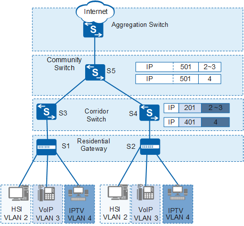
1:1 VLAN mapping applies to the network shown in Figure 1.
In the networking diagram shown in Figure 1, services (HSI, IPTV, and VoIP) of each user are transmitted on different VLANs. Same services are transmitted on the same C-VLAN. To differentiate users, deploy Corridor Switch to allow the same services used by different users to be transmitted on different VLANs, which implements 1:1 VLAN mapping. 1:1 VLAN mapping requires a large number of VLANs to isolate services of different users; however, the VLAN quantity provided by the network access device at the aggregation layer is limited. To resolve this problem, configure the VLAN aggregation function to allow the same services to be transmitted on the same VLAN (N:1 VLAN mapping).
2:1 VLAN mapping
When the interface receives a double-tagged packet, the interface maps the outer VLAN tag in the packet to an S-VLAN tag and transparently transmits the inner VLAN tag.
2:1 VLAN mapping applies to the network shown in Figure 2.
In the networking diagram shown in Figure 2, Residential Gateway, Corridor Switch, and Community Switch are connected to the aggregation layer on the network. To differentiate users and services to facilitate network management and charging, configure the QinQ function for Corridor Switch. To save VLAN resources, configure VLAN mapping on Community Switch to transmit the same services on the same VLAN.
2:2 VLAN mapping
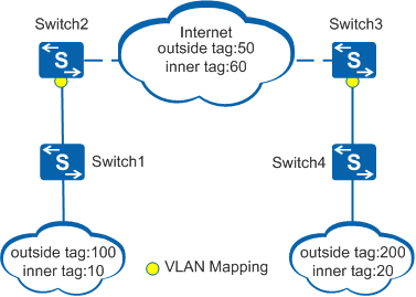
2:2 VLAN mapping applies to the network shown in Figure 3.
In the networking diagram shown in Figure 3, QinQ is used to send double-tagged packets, which prevents the conflict between C-VLAN IDs and S-VLAN IDs and differentiates services and users. However, the interface will discard the packets because C-VLAN IDs are different from S-VLAN IDs. To ensure communication continuity, configure 2:2 VLAN mapping on the PE and replace double C-VLAN tags with double S-VLAN tags.