Understanding VLAN Mapping
Working Mechanism
- Tagged packed: Based on the VLAN mapping mode, the switch determines whether a single tag, double tags, or the outer tag is to be replaced. The switch then learns the MAC addresses in the packet. The switch updates the MAC address entries in the VLAN mapping table based on the source MAC address and mapped VLAN ID. It then searches for the MAC address entries based on the destination MAC address and the mapped VLAN ID. If the destination MAC address matches an entry, the switch forwards the packet through the corresponding outbound interface. If not, the switch broadcasts the packet in the specified VLAN.
- Untagged packet: Based on the VLAN creation mode, the switch determines whether to add a VLAN tag. If the packet can be added to a VLAN, the switch adds a VLAN tag to it and learns the MAC addresses. The switch then performs Layer 2 forwarding based on the destination MAC address. If the packet cannot be added to a VLAN, the switch either delivers the packet to the CPU or discards it.
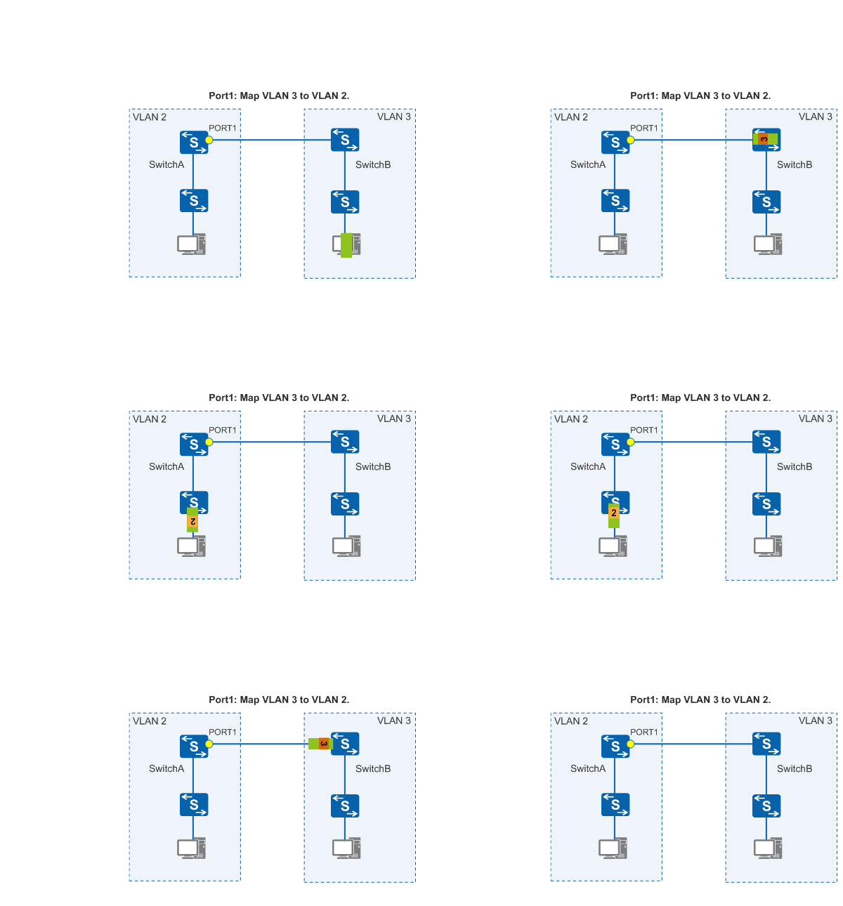
Figure 1 shows VLAN mapping between VLAN 2 and VLAN 3 configured on PORT 1. Before sending packets from VLAN 2 to VLAN 3, PORT 1 replaces the VLAN tags with VLAN 3 tags. When receiving packets from VLAN 3 to VLAN 2, PORT 1 replaces the VLAN tags with VLAN 2 tags. This implements communication between devices in VLAN 2 and VLAN 3.
If devices in two VLANs need to communicate based on VLAN mapping, the IP addresses of these devices must be on the same network segment. If their IP addresses are on different network segments, communication between these devices must be implemented using Layer 3 routes, which makes VLAN mapping invalid.
VLAN Mapping Mode
1 to 1 VLAN mapping
When the interface on a device configured with VLAN mapping receives a single-tagged packet, the interface maps the VLAN tag in the packet to an S-VLAN tag. 1:1 VLAN mapping maps a C-VLAN tag to an S-VLAN tag, whereas N:1 VLAN mapping maps multiple C-VLAN tags to an S-VLAN tag.
2 to 1 VLAN mapping
When the interface on a device configured with VLAN mapping receives a double-tagged packet, the interface maps the outer VLAN tag to an S-VLAN tag and transparently transmits the inner VLAN tag. The interface configured with 1:1 VLAN mapping maps an outer VLAN tag to an S-VLAN tag and transparently transmits the inner VLAN tag. The interface configured with N:1 VLAN mapping maps different outer VLAN tags of packets to the same S-VLAN tag and transparently transmits the inner VLAN tag. Only one outer VLAN tag can be mapped to an S-VLAN tag at a time; therefore, to achieve N:1 VLAN mapping, perform this configuration for multiple times
2 to 2 VLAN mapping
When the interface on a device configured with VLAN mapping receives a double-tagged packet, the interface maps the double VLAN tags to the double S-VLAN tags.
MQC-based VLAN mapping uses a traffic classifier to classify packets based on VLAN IDs. It associates the traffic classifier with a traffic behavior defining VLAN mapping so that the switch can re-mark the VLAN ID in packets matching the traffic classifier. MQC-based VLAN mapping implements differentiated services.
