Example for Configuring a Local CCC Connection
Networking Requirements
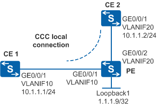
As shown in Figure 1, sites of an enterprise at different geographical locations connect to a PE on an ISP network through CE1 and CE2. To simplify the configuration, the enterprise requires that the two CEs communicate with each other as if through a LAN. The enterprise will not increase sites in the future and wants to use exclusive VPN resources on the ISP network to increase data security.
A local CCC connection can be set up between CE1 and CE2 to exchange Layer 2 information directly.

By default, LNP is enabled globally on the device. If a VLANIF interface is used as an AC-side interface for L2VPN, the configuration conflicts with LNP. In this case, run the lnp disable command in the system view to disable LNP.
The lnp disable command has no impact on services before the device restarts. After the device restarts, the device can only forward packets from the VLANs specified by the port default vlan command at Layer 2. The port default vlan 1 command is configured by default, so only packets of VLAN 1 can be forwarded at Layer 2.
Configuration Roadmap
The enterprise requires that the two CEs communicate with each other as if through a LAN. The VPN in VLL mode can be used. A local CCC connection can be set up between the CEs to implement the VLL VPN networking because the enterprise will not increase sites in the future and the two CEs are connected to the same PE.
The configuration roadmap is as follows:
Configure the basic MPLS capabilities on the PE and enable MPLS L2VPN. Enabling MPLS L2VPN is the prerequisite for VLL configuration.
Create a local connection between CE1 and CE2 on the PE. The local CCC connection is bidirectional, so only one connection is required.
Procedure
- Configure VLANs that the interfaces on CE, PE, and P devices belong to and assign an IP address to each VLANIF interface according to Figure 1.
# Configure CE1.
<HUAWEI> system-view
[HUAWEI] sysname CE1
[CE1] vlan batch 10
[CE1] interface gigabitethernet 0/0/1
[CE1-GigabitEthernet0/0/1] port link-type trunk
[CE1-GigabitEthernet0/0/1] port trunk allow-pass vlan 10
[CE1-GigabitEthernet0/0/1] quit
[CE1] interface vlanif 10
[CE1-Vlanif10] ip address 10.1.1.1 24
[CE1-Vlanif10] quit
# Configure CE2.
<HUAWEI> system-view
[HUAWEI] sysname CE2
[CE2] vlan batch 20
[CE2] interface gigabitethernet 0/0/1
[CE2-GigabitEthernet0/0/1] port link-type trunk
[CE2-GigabitEthernet0/0/1] port trunk allow-pass vlan 20
[CE2-GigabitEthernet0/0/1] quit
[CE2] interface vlanif 20
[CE2-Vlanif20] ip address 10.1.1.2 24
[CE2-Vlanif20] quit
The packets sent from a CE to a PE must have VLAN tags.
# Configure PE.
<HUAWEI> system-view
[HUAWEI] sysname PE
[PE] vlan batch 10 20
[PE] interface gigabitethernet 0/0/1
[PE-GigabitEthernet0/0/1] port link-type trunk
[PE-GigabitEthernet0/0/1] port trunk allow-pass vlan 10
[PE-GigabitEthernet0/0/1] quit
[PE] interface gigabitethernet 0/0/2
[PE-GigabitEthernet0/0/2] port link-type trunk
[PE-GigabitEthernet0/0/2] port trunk allow-pass vlan 20
[PE-GigabitEthernet0/0/2] quit
- Configure the basic MPLS capabilities on the PE and enable MPLS L2VPN.
# Configure PE.
[PE] interface loopback 1
[PE-LoopBack1] ip address 1.1.1.9 32
[PE-LoopBack1] quit
[PE] mpls lsr-id 1.1.1.9
[PE] mpls
[PE-mpls] quit
[PE] mpls l2vpn
[PE-l2vpn] quit
- Create a local CCC connection between CE1 and CE2 on the PE.
# Configure PE. In this example, a VLANIF interface is used as the AC-side interface, so you need to run the lnp disable command in the system view before performing the following steps. If you cannot disable LNP on the live network, do not use a VLANIF interface as the AC-side interface.
[PE] interface vlanif 10
[PE-Vlanif10] quit
[PE] interface vlanif 20
[PE-Vlanif20] quit
[PE] ccc ce1-ce2 interface vlanif 10 out-interface vlanif 20
- Verify the configuration.
After completing the configuration, check the CCC connection information on the PE. The command output shows that a local CCC connection has been set up and the status is Up.
[PE] display vll ccc
total  ccc vc : 1
local  ccc vc : 1,  1 up
remote ccc vc : 0,  0 up

name: ce1-ce2, type: local, state: up,
intf1: Vlanif10 (up), access-port: false

intf2: Vlanif20 (up), access-port: false
VC last up time : 2010/07/24 12:31:31
VC total up time: 0 days, 2 hours, 12 minutes, 51 seconds
Run the display l2vpn ccc-interface vc-type all command on the PE. The command output shows that the VC type is ccc and the VC status is up.
[PE] display l2vpn ccc-interface vc-type all
Total ccc-interface of CCC : 2
up (2), down (0)
Interface                     Encap Type               State     VC Type
Vlanif10                      ethernet                 up        ccc
Vlanif20                      ethernet                 up        ccc
CE1 and CE2 can ping each other.
[CE1] ping 10.1.1.2
  PING 10.1.1.2: 56  data bytes, press CTRL_C to break
    Reply from 10.1.1.2: bytes=56 Sequence=1 ttl=255 time=180 ms
    Reply from 10.1.1.2: bytes=56 Sequence=2 ttl=255 time=60 ms
    Reply from 10.1.1.2: bytes=56 Sequence=3 ttl=255 time=10 ms
    Reply from 10.1.1.2: bytes=56 Sequence=4 ttl=255 time=70 ms
    Reply from 10.1.1.2: bytes=56 Sequence=5 ttl=255 time=60 ms

  --- 10.1.1.2 ping statistics ---
    5 packet(s) transmitted
    5 packet(s) received
    0.00% packet loss
    round-trip min/avg/max = 10/76/180 ms
Configuration Files
CE1 configuration file
#
sysname CE1
#
vlan batch 10
#
interface Vlanif10
 ip address 10.1.1.1 255.255.255.0
#
interface GigabitEthernet0/0/1
 port link-type trunk
 port trunk allow-pass vlan 10
#
return
PE configuration file

The lnp disable command has no impact on services before the device restarts. After the device restarts, the device can only forward packets from the VLANs specified by the port default vlan command at Layer 2. The port default vlan 1 command is configured by default, so only packets of VLAN 1 can be forwarded at Layer 2.
#
sysname PE
#
vlan batch 10 20
#
lnp disable #
mpls lsr-id 1.1.1.9
mpls
#
mpls l2vpn
#
interface Vlanif10
#
interface Vlanif20
#
interface GigabitEthernet0/0/1
 port link-type trunk
 port trunk allow-pass vlan 10
#
interface GigabitEthernet0/0/2
 port link-type trunk
 port trunk allow-pass vlan 20
#
ccc ce1-ce2 interface Vlanif10 out-interface Vlanif20
#
interface LoopBack1
 ip address 1.1.1.9 255.255.255.255
#
return
CE2 configuration file
#
sysname CE2
#
vlan batch 20
#
interface Vlanif20
 ip address 10.1.1.2 255.255.255.0
#
interface GigabitEthernet0/0/1
 port link-type trunk
 port trunk allow-pass vlan 20
#
return