Example for Configuring a Remote CCC Connection
Networking Requirements
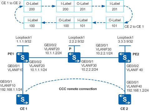
As shown in Figure 1, sites of an enterprise at different geographical locations connect to the MPLS network of an ISP through CE1 and CE2. To simplify the configuration, the enterprise requires that the two CEs communicate with each other as if through a LAN. The enterprise will not increase sites in the future and wants to use exclusive VPN resources on the ISP network to increase data security.
A remote CCC connection can be set up between CE1 and CE2 to exchange Layer 2 information directly.

By default, LNP is enabled globally on the device. If a VLANIF interface is used as an AC-side interface for L2VPN, the configuration conflicts with LNP. In this case, run the lnp disable command in the system view to disable LNP.
The lnp disable command has no impact on services before the device restarts. After the device restarts, the device can only forward packets from the VLANs specified by the port default vlan command at Layer 2. The port default vlan 1 command is configured by default, so only packets of VLAN 1 can be forwarded at Layer 2.
Configuration Roadmap
The enterprise requires that the two CEs communicate with each other as if through a LAN. The enterprise will not increase sites in the future. Therefore, a remote CCC connection can be set up between the CEs so that the enterprise can use VPN resources of the ISP to increase data security.
The configuration roadmap is as follows:
Enable MPLS L2VPN on the PEs. (MPLS L2VPN does not need to be enabled on the P device). Enabling MPLS L2VPN is the prerequisite for VLL configuration.
Create a remote CCC connection on the two PEs. To create a remote CCC connection, specify the inbound interface, inbound label, outbound label, and next hop.
Configure static LSPs in the forward and reverse directions, which are exclusively used by the CCC connection between the PEs.
Procedure
- Configure VLANs that each interface belongs to and assign an IP address to each VLANIF interface according to Figure 1.
# Configure CE1. The configuration on CE2, PE1, P, and PE2 is similar to the configuration on CE1 and is not mentioned here.
<HUAWEI> system-view
[HUAWEI] sysname CE1
[CE1] vlan batch 10
[CE1] interface vlanif 10
[CE1-Vlanif10] ip address 192.168.1.1 255.255.255.0
[CE1-Vlanif10] quit
[CE1] interface gigabitethernet 0/0/1
[CE1-GigabitEthernet0/0/1] port link-type trunk
[CE1-GigabitEthernet0/0/1] port trunk allow-pass vlan 10
[CE1-GigabitEthernet0/0/1] quit
The packets sent from a CE to a PE must have VLAN tags.
- Configure the basic MPLS capabilities on the MPLS backbone network.
# Configure PE1.
[PE1] interface loopback 1
[PE1-LoopBack1] ip address 1.1.1.9 32
[PE1-LoopBack1] quit
[PE1] mpls lsr-id 1.1.1.9
[PE1] mpls
[PE1-mpls] quit
[PE1] interface vlanif 20
[PE1-Vlanif20] mpls
[PE1-Vlanif20] quit
# Configure the P.
[P] interface loopback 1
[P-LoopBack1] ip address 2.2.2.9 32
[P-LoopBack1] quit
[P] mpls lsr-id 2.2.2.9
[P] mpls
[P-mpls] quit
[P] interface vlanif 20
[P-Vlanif20] mpls
[P-Vlanif20] quit
[P] interface vlanif 30
[P-Vlanif30] mpls
[P-Vlanif30] quit
# Configure PE2.
[PE2] interface loopback 1
[PE2-LoopBack1] ip address 3.3.3.9 32
[PE2-LoopBack1] quit
[PE2] mpls lsr-id 3.3.3.9
[PE2] mpls
[PE2-mpls] quit
[PE2] interface vlanif 30
[PE2-Vlanif30] mpls
[PE2-Vlanif30] quit
- Create the remote CCC connection between the two PEs.
# Configure PE1: Enable MPLS L2VPN globally and create the remote CCC connection from CE1 to CE2. Connect the inbound interface of PE1 to CE1 and the outbound interface of PE1 to the P. Set the incoming label to 100 and the outgoing label to 200. In this example, a VLANIF interface is used as the AC-side interface, so you need to run the lnp disable command in the system view before performing the following steps. If you cannot disable LNP on the live network, do not use a VLANIF interface as the AC-side interface.
[PE1] mpls l2vpn
[PE1-l2vpn] quit
[PE1] interface vlanif 10
[PE1-Vlanif10] quit
[PE1] ccc CE1-CE2 interface vlanif 10 in-label 100 out-label 200 nexthop 10.1.1.2
# Configure PE2: Enable mpls l2vpn globally and create the remote CCC connection from CE2 to CE1. Connect the inbound interface of PE2 to CE2 and the outbound interface of PE2 to the P. Set the incoming label to 201 and the outgoing label to 101. In this example, a VLANIF interface is used as the AC-side interface, so you need to run the lnp disable command in the system view before performing the following steps. If you cannot disable LNP on the live network, do not use a VLANIF interface as the AC-side interface.
[PE2] mpls l2vpn
[PE2-l2vpn] quit
[PE2] interface vlanif 40
[PE2-Vlanif40] quit
[PE2] ccc CE2-CE1 interface vlanif 40 in-label 201 out-label 101 nexthop 10.2.2.2
- Configure static LSPs on P for forwarding packets.
# Configure P: Configure a static LSP for forwarding packets from PE1 to PE2, and configure another static LSP for forwarding packets from PE2 to PE1.
[P] static-lsp transit PE1-PE2 incoming-interface vlanif 20 in-label 200 nexthop 10.2.2.1 out-label 201
[P] static-lsp transit PE2-PE1 incoming-interface vlanif 30 in-label 101 nexthop 10.1.1.1 out-label 100
- Verify the configuration.
After completing the configuration, check information about the CCC connection on the PEs. You can find that a remote CCC connection is set up on each of PE1 and PE2 and the status of the connection is Up.
[PE1] display vll ccc
total  ccc vc : 1
local  ccc vc : 0,  0 up
remote ccc vc : 1,  1 up

name: CE1-CE2, type: remote, state: up,
intf: Vlanif10 (up), in-label: 100 , out-label: 200 , nexthop: 10.1.1.2
VC last up time : 2009/10/09 17:35:14
VC total up time: 0 days, 3 hours, 22 minutes, 55 seconds
[PE2] display vll ccc
total  ccc vc : 1
local  ccc vc : 0,  0 up
remote ccc vc : 1,  1 up

name: CE2-CE1, type: remote, state: up,
intf: Vlanif40 (up), in-label: 201 , out-label: 101 , nexthop: 10.2.2.2
VC last up time : 2009/10/09 17:35:14
VC total up time: 0 days, 3 hours, 22 minutes, 55 seconds
Run the display l2vpn ccc-interface vc-type ccc command on PE. The command output shows that the VC type is ccc and the VC status is up. The command output of PE1 is used as an example.
[PE1] display l2vpn ccc-interface vc-type ccc
Total ccc-interface of CCC : 1
up (1), down (0)
Interface                     Encap Type               State     VC Type
Vlanif10                      ethernet                 up        ccc
Run the display mpls lsp command on the P device to view the label and interface information of the two static LSPs.
[P] display mpls lsp
-------------------------------------------------------------------------------
                 LSP Information: STATIC LSP
-------------------------------------------------------------------------------
FEC                In/Out Label  In/Out IF                      Vrf Name
-/-                200/201       Vlanif20/Vlanif30
-/-                101/100       Vlanif30/Vlanif20
CE1 and CE2 can ping each other.
The command output of CE1 is used as an example.
[CE1] ping 192.168.1.2
  PING 192.168.1.2: 56  data bytes, press CTRL_C to break
    Reply from 192.168.1.2: bytes=56 Sequence=1 ttl=255 time=58 ms
    Reply from 192.168.1.2: bytes=56 Sequence=2 ttl=255 time=67 ms
    Reply from 192.168.1.2: bytes=56 Sequence=3 ttl=255 time=52 ms
    Reply from 192.168.1.2: bytes=56 Sequence=4 ttl=255 time=69 ms
    Reply from 192.168.1.2: bytes=56 Sequence=5 ttl=255 time=92 ms

  --- 192.168.1.2 ping statistics ---
    5 packet(s) transmitted
    5 packet(s) received
    0.00% packet loss
    round-trip min/avg/max = 52/67/92 ms
Configuration Files
CE1 configuration file
#
sysname CE1
#
vlan batch 10
#
interface Vlanif10
 ip address 192.168.1.1 255.255.255.0
#
interface GigabitEthernet0/0/1
 port link-type trunk
 port trunk allow-pass vlan 10
#
return
PE1 configuration file

The lnp disable command has no impact on services before the device restarts. After the device restarts, the device can only forward packets from the VLANs specified by the port default vlan command at Layer 2. The port default vlan 1 command is configured by default, so only packets of VLAN 1 can be forwarded at Layer 2.
#
sysname PE1
#
vlan batch 10 20
#
lnp disable #mpls lsr-id 1.1.1.9
mpls
#
mpls l2vpn
#
interface Vlanif10
#
interface Vlanif20
 ip address 10.1.1.1 255.255.255.0
 mpls
#
interface GigabitEthernet0/0/1
 port link-type trunk
 port trunk allow-pass vlan 10
#
interface GigabitEthernet0/0/2
 port link-type trunk
 port trunk allow-pass vlan 20
#
ccc CE1-CE2 interface Vlanif10 in-label 100 out-label 200 nexthop 10.1.1.2
#
interface LoopBack1
 ip address 1.1.1.9 255.255.255.255
#
return
P configuration file
#
sysname P
#
vlan batch 20 30
#
mpls lsr-id 2.2.2.9
mpls
#
interface Vlanif20
 ip address 10.1.1.2 255.255.255.0
 mpls
#
interface Vlanif30
 ip address 10.2.2.2 255.255.255.0
 mpls
#
interface GigabitEthernet0/0/1
 port link-type trunk
 port trunk allow-pass vlan 30
#
interface GigabitEthernet0/0/2
 port link-type trunk
 port trunk allow-pass vlan 20
#
interface LoopBack1
 ip address 2.2.2.9 255.255.255.255
#
static-lsp transit PE1-PE2 incoming-interface Vlanif20 in-label 200 nexthop 10.2.2.1 out-label 201
static-lsp transit PE2-PE1 incoming-interface Vlanif30 in-label 101 nexthop 10.1.1.1 out-label 100
#
return
PE2 configuration file
The lnp disable command has no impact on services before the device restarts. After the device restarts, the device can only forward packets from the VLANs specified by the port default vlan command at Layer 2. The port default vlan 1 command is configured by default, so only packets of VLAN 1 can be forwarded at Layer 2.
#
sysname PE2
#
vlan batch 30 40
#
lnp disable #mpls lsr-id 3.3.3.9
mpls
#
mpls l2vpn
#
interface Vlanif30
 ip address 10.2.2.1 255.255.255.0
 mpls
#
interface Vlanif40
#
interface GigabitEthernet0/0/1
 port link-type trunk
 port trunk allow-pass vlan 30
#
interface GigabitEthernet0/0/2
 port link-type trunk
 port trunk allow-pass vlan 40
#
ccc CE2-CE1 interface Vlanif40 in-label 201 out-label 101 nexthop 10.2.2.2
#
interface LoopBack1
 ip address 3.3.3.9 255.255.255.255
#
return
CE2 configuration file
#
sysname CE2
#
vlan batch 40
#
interface Vlanif40
 ip address 192.168.1.2 255.255.255.0
#
interface GigabitEthernet0/0/1
 port link-type trunk
 port trunk allow-pass vlan 40
#
return