Example for Configuring a VLL Connection in SVC Mode
Networking Requirements
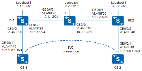
The MPLS network of an ISP provides the L2VPN service for sites of two users. Each user has two sites at fixed locations, which connect to the MPLS network through CE1 and CE2. The users require that hosts in different sites but the same LAN can communicate at Layer 2.

By default, LNP is enabled globally on the device. If a VLANIF interface is used as an AC-side interface for L2VPN, the configuration conflicts with LNP. In this case, run the lnp disable command in the system view to disable LNP.
The lnp disable command has no impact on services before the device restarts. After the device restarts, the device can only forward packets from the VLANs specified by the port default vlan command at Layer 2. The port default vlan 1 command is configured by default, so only packets of VLAN 1 can be forwarded at Layer 2.
Configuration Roadmap
The two PEs have fixed users so the inner VC labels for the users can be specified manually. Therefore, a VLL in SVC mode is recommended.
The configuration roadmap is as follows:
Configure an IGP on the MPLS backbone network to implement IP interworking.
Configure basic MPLS functions and LDP on the MPLS backbone network and set up an LDP LSP tunnel. The LDP LSP tunnel is used as a dedicated tunnel to transmit private network data on the public network.
On the PEs, enable MPLS L2VPN, create a static VC connection, and manually configure VC labels. Enabling MPLS L2VPN is the prerequisite for VLL configuration, and creating a static VC connection is the most important step in configuring VLL in SVC mode.
Procedure
- Configure VLANs that each interface belongs to and assign an IP address to each VLANIF interface according to Figure 1.
# Configure CE1. The configuration on CE2, PE1, P and PE2 is similar to the configuration on CE1 and is not mentioned here.
<HUAWEI> system-view
[HUAWEI] sysname CE1
[CE1] vlan batch 10
[CE1] interface vlanif 10
[CE1-Vlanif10] ip address 192.168.1.1 255.255.255.0
[CE1-Vlanif10] quit
[CE1] interface gigabitethernet 0/0/1
[CE1-GigabitEthernet0/0/1] port link-type trunk
[CE1-GigabitEthernet0/0/1] port trunk allow-pass vlan 10
[CE1-GigabitEthernet0/0/1] quit
- Configure IGP on the MPLS backbone network. (In this example, OSPF is used.)
When configuring OSPF, advertise the 32-bit addresses of loopback interfaces on PEs and P. The loopback interface addresses are the LSR IDs.
# Configure PE1. The configuration on P and PE2 is similar to the configuration on PE1 and is not mentioned here.
[PE1] interface loopback 1
[PE1-LoopBack1] ip address 1.1.1.9 32
[PE1-LoopBack1] quit
[PE1] ospf 1
[PE1-ospf-1] area 0
[PE1-ospf-1-area-0.0.0.0] network 10.1.1.0 0.0.0.255
[PE1-ospf-1-area-0.0.0.0] network 1.1.1.9 0.0.0.0
[PE1-ospf-1-area-0.0.0.0] quit
[PE1-ospf-1] quit
- Configure basic MPLS functions and LDP on the MPLS backbone network, and set up LDP LSPs.
# Configure PE1.
[PE1] mpls lsr-id 1.1.1.9
[PE1] mpls
[PE1-mpls] quit
[PE1] mpls ldp
[PE1-mpls-ldp] quit
[PE1] interface vlanif 20
[PE1-Vlanif20] mpls
[PE1-Vlanif20] mpls ldp
[PE1-Vlanif20] quit
# Configure the P.
[P] mpls lsr-id 2.2.2.9
[P] mpls
[P-mpls] quit
[P] mpls ldp
[P-mpls-ldp] quit
[P] interface vlanif 20
[P-Vlanif20] mpls
[P-Vlanif20] mpls ldp
[P-Vlanif20] quit
[P] interface vlanif 30
[P-Vlanif30] mpls
[P-Vlanif30] mpls ldp
[P-Vlanif30] quit
# Configure PE2.
[PE2] mpls lsr-id 3.3.3.9
[PE2] mpls
[PE2-mpls] quit
[PE2] mpls ldp
[PE2-mpls-ldp] quit
[PE2] interface vlanif 30
[PE2-Vlanif30] mpls
[PE2-Vlanif30] mpls ldp
[PE2-Vlanif30] quit
After completing the configuration, LDP sessions are set up between PE1, P, and PE2. Run the display mpls ldp session command. The command output shows that the status of the LDP session is Operational.
The command output of PE1 is used as an example.
[PE1] display mpls ldp session

 LDP Session(s) in Public Network
 Codes: LAM(Label Advertisement Mode), SsnAge Unit(DDDD:HH:MM)
 A '*' before a session means the session is being deleted.
 ------------------------------------------------------------------------------
 PeerID             Status      LAM  SsnRole  SsnAge      KASent/Rcv
 ------------------------------------------------------------------------------
 2.2.2.9:0          Operational DU   Passive  0000:00:05  22/22
 ------------------------------------------------------------------------------
 TOTAL: 1 session(s) Found.
- Enable MPLS L2VPN and create static VCs on PEs.
# Configure PE1: Create a static VC on VLANIF 10, which is connected to CE1.In this example, a VLANIF interface is used as the AC-side interface, so you need to run the lnp disable command in the system view before performing the following steps. If you cannot disable LNP on the live network, do not use a VLANIF interface as the AC-side interface.
[PE1] mpls l2vpn
[PE1-l2vpn] quit
[PE1] interface vlanif 10
[PE1-Vlanif10] mpls static-l2vc destination 3.3.3.9 transmit-vpn-label 100 receive-vpn-label 200
[PE1-Vlanif10] quit
# Configure PE2: Create a static VC on VLANIF 40, which is connected to CE2.In this example, a VLANIF interface is used as the AC-side interface, so you need to run the lnp disable command in the system view before performing the following steps. If you cannot disable LNP on the live network, do not use a VLANIF interface as the AC-side interface.
[PE2] mpls l2vpn
[PE2-l2vpn] quit
[PE2] interface vlanif 40
[PE2-Vlanif40] mpls static-l2vc destination 1.1.1.9 transmit-vpn-label 200 receive-vpn-label 100
[PE2-Vlanif40] quit
- Verify the configuration.
View the L2VPN connection information of the SVC on the PE. The command output shows that a static L2VC connection is established.
The command output of PE1 is used as an example.
[PE1] display mpls static-l2vc interface vlanif 10
 *Client Interface     : Vlanif10 is up
  AC Status            : up
  VC State             : up
  VC ID                : 0
  VC Type              : VLAN
  Destination          : 3.3.3.9
  Transmit VC Label    : 100
  Receive VC Label     : 200
  Label Status         : 0
  Token Status         : 0
  Control Word         : Disable
  VCCV Capability      : alert ttl lsp-ping bfd
  active state         : active
  Link State           : up
  Tunnel Policy        : --
  PW Template Name     : --
  Main or Secondary    : Main
  load balance type    : flow
  Access-port          : false
  VC tunnel/token info : 1 tunnels/tokens
  NO.0  TNL Type       : lsp   , TNL ID : 0x48000018
  Backup TNL Type      : lsp   , TNL ID : 0x0
  Create time          : 0 days, 0 hours, 4 minutes, 31 seconds
  UP time              : 0 days, 0 hours, 2 minutes, 14 seconds
  Last change time     : 0 days, 0 hours, 2 minutes, 14 seconds
  VC last up time      : 2012/08/16 19:05:13
  VC total up time     : 0 days, 0 hours, 2 minutes, 14 seconds
  CKey                 : 4
  NKey                 : 3
  Diffserv Mode        : uniform
  Service Class        : be
  Color                : --
  DomainId             : --
  Domain Name          : --
  BFD for PW           : unavailable
Run the display l2vpn ccc-interface vc-type static-vc up command. The command output shows that the VC type is static-vc and the VC status is up. The command output of PE1 is used as an example.
[PE1] display l2vpn ccc-interface vc-type static-vc up
Total ccc-interface of SVC VC: 1
up (1), down (0)
Interface                     Encap Type               State     VC Type
Vlanif10                      vlan                     up        static-vc
CE1 and CE2 can ping each other.
[CE1] ping 192.168.1.2
  PING 192.168.1.2: 56  data bytes, press CTRL_C to break
    Reply from 192.168.1.2: bytes=56 Sequence=1 ttl=255 time=46 ms
    Reply from 192.168.1.2: bytes=56 Sequence=2 ttl=255 time=91 ms
    Reply from 192.168.1.2: bytes=56 Sequence=3 ttl=255 time=74 ms
    Reply from 192.168.1.2: bytes=56 Sequence=4 ttl=255 time=88 ms
    Reply from 192.168.1.2: bytes=56 Sequence=5 ttl=255 time=82 ms

  --- 192.168.1.2 ping statistics ---
    5 packet(s) transmitted
    5 packet(s) received
    0.00% packet loss
    round-trip min/avg/max = 46/76/91 ms
Configuration Files
CE1 configuration file
#
sysname CE1
#
vlan batch 10
#
interface Vlanif10
 ip address 192.168.1.1 255.255.255.0
#
interface GigabitEthernet0/0/1
 port link-type trunk
 port trunk allow-pass vlan 10
#
return
PE1 configuration file

The lnp disable command has no impact on services before the device restarts. After the device restarts, the device can only forward packets from the VLANs specified by the port default vlan command at Layer 2. The port default vlan 1 command is configured by default, so only packets of VLAN 1 can be forwarded at Layer 2.
#
sysname PE1
#
vlan batch 10 20
#
lnp disable #mpls lsr-id 1.1.1.9
mpls
#
mpls l2vpn
#
mpls ldp
#
interface Vlanif10
 mpls static-l2vc destination 3.3.3.9 transmit-vpn-label 100 receive-vpn-label 200
#
interface Vlanif20
 ip address 10.1.1.1 255.255.255.0
 mpls
 mpls ldp
#
interface GigabitEthernet0/0/1
 port link-type trunk
 port trunk allow-pass vlan 10
#
interface GigabitEthernet0/0/2
 port link-type trunk
 port trunk allow-pass vlan 20
#
interface LoopBack1
 ip address 1.1.1.9 255.255.255.255
#
ospf 1
 area 0.0.0.0
  network 1.1.1.9 0.0.0.0
  network 10.1.1.0 0.0.0.255
#
return
P configuration file
#
sysname P
#
vlan batch 20 30
#
mpls lsr-id 2.2.2.9
mpls
#
mpls ldp
#
interface Vlanif20
 ip address 10.1.1.2 255.255.255.0
 mpls
 mpls ldp
#
interface Vlanif30
 ip address 10.2.2.2 255.255.255.0
 mpls
 mpls ldp
#
interface GigabitEthernet0/0/1
 port link-type trunk
 port trunk allow-pass vlan 30
#
interface GigabitEthernet0/0/2
 port link-type trunk
 port trunk allow-pass vlan 20
#
interface LoopBack1
 ip address 2.2.2.9 255.255.255.255
#
ospf 1
 area 0.0.0.0
  network 2.2.2.9 0.0.0.0
  network 10.1.1.0 0.0.0.255
  network 10.2.2.0 0.0.0.255
#
return
PE2 configuration file
The lnp disable command has no impact on services before the device restarts. After the device restarts, the device can only forward packets from the VLANs specified by the port default vlan command at Layer 2. The port default vlan 1 command is configured by default, so only packets of VLAN 1 can be forwarded at Layer 2.
#
sysname PE2
#
vlan batch 30 40
#
lnp disable #mpls lsr-id 3.3.3.9
mpls
#
mpls l2vpn
#
mpls ldp
#
interface Vlanif30
 ip address 10.2.2.1 255.255.255.0
 mpls
 mpls ldp
#
interface Vlanif40
 mpls static-l2vc destination 1.1.1.9 transmit-vpn-label 200 receive-vpn-label 100
#
interface GigabitEthernet0/0/1
 port link-type trunk
 port trunk allow-pass vlan 30
#
interface GigabitEthernet0/0/2
 port link-type trunk
 port trunk allow-pass vlan 40
#
interface LoopBack1
 ip address 3.3.3.9 255.255.255.255
#
ospf 1
 area 0.0.0.0
  network 3.3.3.9 0.0.0.0
  network 10.2.2.0 0.0.0.255
#
return
CE2 configuration file
#
sysname CE2
#
vlan batch 40
#
interface Vlanif40
 ip address 192.168.1.2 255.255.255.0
#
interface GigabitEthernet0/0/1
 port link-type trunk
 port trunk allow-pass vlan 40
#
return