Example for Configuring a Local VLL Connection in Kompella Mode
Networking Requirements
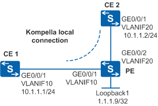
As shown in Figure 1, sites of an enterprise at different geographical locations connect to a PE on the ISP network through CE1 and CE2. To simplify the configuration, the enterprise requires that the two CEs communicate with each other as if through a LAN. The enterprise may add new sites in the future, and the locations and quantities of sites to be added are not yet determined. The enterprise wants to use exclusive VPN resources of the ISP to ensure data security.

By default, LNP is enabled globally on the device. If a VLANIF interface is used as an AC-side interface for L2VPN, the configuration conflicts with LNP. In this case, run the lnp disable command in the system view to disable LNP.
The lnp disable command has no impact on services before the device restarts. After the device restarts, the device can only forward packets from the VLANs specified by the port default vlan command at Layer 2. The port default vlan 1 command is configured by default, so only packets of VLAN 1 can be forwarded at Layer 2.
Configuration Roadmap
The enterprise requires that the two CEs communicate with each other like on a LAN. This requirement can be satisfied by a VLL solution. The enterprise may add new sites in the future, so a local VLL connection can be set up between CE1 and CE2 in Kompella mode.
The configuration roadmap is as follows:
Enable MPLS on the PEs.
Configure an L2VPN instance and set up a local VLL connection in Kompella mode.
Procedure
- Configure VLANs that each interface belongs to and assign an IP address to each VLANIF interface according to Figure 1.
# Configure CE1. The configuration on PE and CE2 is similar to the configuration on CE1 and is not mentioned here.
<HUAWEI> system-view
[HUAWEI] sysname CE1
[CE1] vlan batch 10
[CE1] interface vlanif 10
[CE1-Vlanif10] ip address 10.1.1.1 255.255.255.0
[CE1-Vlanif10] quit
[CE1] interface gigabitethernet 0/0/1
[CE1-GigabitEthernet0/0/1] port link-type trunk
[CE1-GigabitEthernet0/0/1] port trunk allow-pass vlan 10
[CE1-GigabitEthernet0/0/1] quit
The configuration details of other devices are not mentioned here.
- Configure a local connection in Kompella mode.
# Configure basic MPLS functions.
[PE] interface loopback 1
[PE-LoopBack1] ip address 1.1.1.9 32
[PE-LoopBack1] quit
[PE] mpls lsr-id 1.1.1.9
[PE] mpls
[PE-mpls] quit
# Configure MPLS L2VPN and CE connections. In this example, a VLANIF interface is used as the AC-side interface, so you need to run the lnp disable command in the system view before performing the following steps. If you cannot disable LNP on the live network, do not use a VLANIF interface as the AC-side interface.
[PE] mpls l2vpn
[PE-l2vpn] quit
[PE] mpls l2vpn vpn1 encapsulation vlan
[PE-mpls-l2vpn-vpn1] route-distinguisher 100:1
[PE-mpls-l2vpn-vpn1] ce ce1 id 1 range 10
[PE-mpls-l2vpn-ce-vpn1-ce1] connection ce-offset 2 interface vlanif 10
[PE-mpls-l2vpn-ce-vpn1-ce1] quit
[PE-mpls-l2vpn-vpn1] ce ce2 id 2 range 10
[PE-mpls-l2vpn-ce-vpn1-ce2] connection ce-offset 1 interface vlanif 20
[PE-mpls-l2vpn-ce-vpn1-ce2] quit
[PE-mpls-l2vpn-vpn1] quit
- Verify the configuration.
After the configuration is complete, run the display mpls l2vpn connection command on the PE. The command output shows that two L2VPN connections have been set up and they are in Up state.
[PE] display mpls l2vpn connection
2 total connections,
connections: 2 up, 0 down, 2 local, 0 remote, 0 unknown

VPN name: vpn1,
2 total connections,
connections: 2 up, 0 down, 2 local, 0 remote, 0 unknown

  CE name: ce1, id: 1,
  Rid type status peer-id         route-distinguisher interface
  primary or not
----------------------------------------------------------------------------
  2   loc  up     ---             ---                 Vlanif10
  primary

  CE name: ce2, id: 2,
  Rid type status peer-id         route-distinguisher interface
  primary or not
----------------------------------------------------------------------------
  1   loc  up     ---             ---                 Vlanif20
  primary
CE1 and CE2 can ping each other.
[CE1] ping 10.1.1.2
  PING 10.1.1.2: 56  data bytes, press CTRL_C to break
    Reply from 10.1.1.2: bytes=56 Sequence=1 ttl=255 time=24 ms
    Reply from 10.1.1.2: bytes=56 Sequence=2 ttl=255 time=26 ms
    Reply from 10.1.1.2: bytes=56 Sequence=3 ttl=255 time=24 ms
    Reply from 10.1.1.2: bytes=56 Sequence=4 ttl=255 time=51 ms
    Reply from 10.1.1.2: bytes=56 Sequence=5 ttl=255 time=48 ms

  --- 10.1.1.2 ping statistics ---
    5 packet(s) transmitted
    5 packet(s) received
    0.00% packet loss
    round-trip min/avg/max = 24/34/51 ms
Configuration Files
CE1 configuration file
#
sysname CE1
#
vlan batch 10
#
interface Vlanif10
 ip address 10.1.1.1 255.255.255.0
#
interface GigabitEthernet0/0/1
 port link-type trunk
 port trunk allow-pass vlan 10
#
return
PE configuration file

The lnp disable command has no impact on services before the device restarts. After the device restarts, the device can only forward packets from the VLANs specified by the port default vlan command at Layer 2. The port default vlan 1 command is configured by default, so only packets of VLAN 1 can be forwarded at Layer 2.
#
sysname PE
#
vlan batch 10 20
#
lnp disable #mpls lsr-id 1.1.1.9
mpls
#
mpls l2vpn
#
interface Vlanif10
#
interface Vlanif20
#
interface GigabitEthernet0/0/1
 port link-type trunk
 port trunk allow-pass vlan 10
#
interface GigabitEthernet0/0/2
 port link-type trunk
 port trunk allow-pass vlan 20
#
mpls l2vpn vpn1 encapsulation vlan
 route-distinguisher 100:1
 ce ce1 id 1 range 10 default-offset 0
  connection ce-offset 2 interface Vlanif10
 ce ce2 id 2 range 10 default-offset 0
  connection ce-offset 1 interface Vlanif20
#
interface LoopBack1
 ip address 1.1.1.9 255.255.255.255
#
return
CE2 configuration file
#
sysname CE2
#
vlan batch 20
#
interface Vlanif20
 ip address 10.1.1.2 255.255.255.0
#
interface GigabitEthernet0/0/1
 port link-type trunk
 port trunk allow-pass vlan 20
#
return