Example for Configuring a Remote VLL Connection in Kompella Mode
Networking Requirements
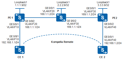
The MPLS network of an ISP provides the L2VPN service for an enterprise user. The ISP needs to reserve VPN resources for eight sites of the enterprise so that new sites can be added easily, using simple configurations, in the future.
A remote VLL connection, as shown in Figure 1, satisfies these requirements.

By default, LNP is enabled globally on the device. If a VLANIF interface is used as an AC-side interface for L2VPN, the configuration conflicts with LNP. In this case, run the lnp disable command in the system view to disable LNP.
The lnp disable command has no impact on services before the device restarts. After the device restarts, the device can only forward packets from the VLANs specified by the port default vlan command at Layer 2. The port default vlan 1 command is configured by default, so only packets of VLAN 1 can be forwarded at Layer 2.
Configuration Roadmap
VPN resources need to be reserved for eight sites to simplify configuration for future network expansion. To meet this requirement, a remote VLL connection can be set up between CE1 and C2 in Kompella mode.
The configuration roadmap is as follows:
Configure an IGP on the PE and P devices on the backbone network to ensure reachability between them.
Configure basic MPLS capabilities and LDP, and set up an LDP LSP tunnel between the PEs. Enable MPLS and LDP on the PE and P devices, and enable LDP on the interfaces between theses devices. The LDP LSP tunnel is used as a dedicated tunnel to transmit private network data on the public network.
Enable MPLS L2VPN and configure BGP L2VPN on PEs.
Configure the VPN instance and CE connections.
Procedure
- Configure VLANs that each interface belongs to and assign an IP address to each VLANIF interface according to Figure 1.
# Configure CE1. The configurations of CE2, PE1, PE2, and the P device are similar to that of CE1, and are not mentioned here.
<HUAWEI> system-view
[HUAWEI] sysname CE1
[CE1] vlan batch 10
[CE1] interface vlanif 10
[CE1-Vlanif10] ip address 192.168.1.1 255.255.255.0
[CE1-Vlanif10] quit
[CE1] interface gigabitethernet 0/0/1
[CE1-GigabitEthernet0/0/1] port link-type trunk
[CE1-GigabitEthernet0/0/1] port trunk allow-pass vlan 10
[CE1-GigabitEthernet0/0/1] quit
- Configure an IGP protocol on the MPLS backbone network.
In this example, OSPF is used as the IGP protocol. When configuring OSPF, advertise the 32-bit addresses of loopback interfaces on PEs and P. The loopback interface addresses are the LSR IDs.
# Configure PE1. The configurations of PE2, and the P device are similar to that of PE1, and are not mentioned here.
[PE1] interface loopback 1
[PE1-LoopBack1] ip address 1.1.1.9 32
[PE1-LoopBack1] quit
[PE1] ospf 1
[PE1-ospf-1] area 0
[PE1-ospf-1-area-0.0.0.0] network 168.1.1.0 0.0.0.255
[PE1-ospf-1-area-0.0.0.0] network 1.1.1.9 0.0.0.0
[PE1-ospf-1-area-0.0.0.0] quit
[PE1-ospf-1] quit
After the configuration is complete, run the display ip routing-table command on each LSR. You can view that the LSRs have learned the routes from each other.
The command output of PE1 is used as an example.
[PE1] display ip routing-table
Route Flags: R - relay, D - download to fib, T - to vpn-instance
------------------------------------------------------------------------------
Routing Tables: Public
         Destinations : 8        Routes : 8

Destination/Mask    Proto  Pre  Cost     Flags NextHop         Interface

        1.1.1.9/32  Direct 0    0           D  127.0.0.1       LoopBack1
        2.2.2.9/32  OSPF   10   1           D  168.1.1.2       Vlanif20
        3.3.3.9/32  OSPF   10   2           D  168.1.1.2       Vlanif20
      127.0.0.0/8   Direct 0    0           D  127.0.0.1       InLoopBack0
      127.0.0.1/32  Direct 0    0           D  127.0.0.1       InLoopBack0
      168.1.1.0/24  Direct 0    0           D  168.1.1.1       Vlanif20
      168.1.1.1/32  Direct 0    0           D  127.0.0.1       Vlanif20
      169.1.1.0/24  OSPF   10   2           D  168.1.1.2       Vlanif20
Run the display ospf peer command, and you can see that the OSPF neighbor relationship is set up and the neighbor status is Full.
Take the display on PE1 for example:
[PE1] display ospf peer OSPF Process 1 with Router ID 1.1.1.9 Neighbors Area 0.0.0.0 interface 168.1.1.1(Vlanif20)'s neighbors Router ID: 2.2.2.9 Address: 168.1.1.2 State: Full Mode:Nbr is Master Priority: 1 DR: 168.1.1.1 BDR: 168.1.1.2 MTU: 0 Dead timer due in 35 sec Retrans timer interval: 5 Neighbor is up for 00:17:12 Authentication Sequence: [ 0 ] - Configure basic MPLS functions and LDP, and set up LDP LSPs.
# Configure PE1.
[PE1] mpls lsr-id 1.1.1.9
[PE1] mpls
[PE1-mpls] quit
[PE1] mpls ldp
[PE1-mpls-ldp] quit
[PE1] interface vlanif 20
[PE1-Vlanif20] mpls
[PE1-Vlanif20] mpls ldp
[PE1-Vlanif20] quit
# Configure the P device.
[P] mpls lsr-id 2.2.2.9
[P] mpls
[P-mpls] quit
[P] mpls ldp
[P-mpls-ldp] quit
[P] interface vlanif 20
[P-Vlanif20] mpls
[P-Vlanif20] mpls ldp
[P-Vlanif20] quit
[P] interface vlanif 30
[P-Vlanif30] mpls
[P-Vlanif30] mpls ldp
[P-Vlanif30] quit
# Configure PE2.
[PE2] mpls lsr-id 3.3.3.9
[PE2] mpls
[PE2-mpls] quit
[PE2] mpls ldp
[PE2-mpls-ldp] quit
[PE2] interface vlanif 30
[PE2-Vlanif30] mpls
[PE2-Vlanif30] mpls ldp
[PE2-Vlanif30] quit
After the configuration is complete, run the display mpls ldp session and display mpls ldp peer commands on each LSR. You can see information about the LDP session and peers.
The command output of PE1 is used as an example.
[PE1] display mpls ldp session

 LDP Session(s) in Public Network
 Codes: LAM(Label Advertisement Mode), SsnAge Unit(DDDD:HH:MM)
 A '*' before a session means the session is being deleted.
 ------------------------------------------------------------------------------
 PeerID             Status      LAM  SsnRole  SsnAge      KASent/Rcv
 ------------------------------------------------------------------------------
 2.2.2.9:0          Operational DU   Passive  0000:00:07  32/32
 ------------------------------------------------------------------------------
 TOTAL: 1 session(s) Found.
[PE1] display mpls ldp peer

LDP Peer Information in Public network
 A '*' before a peer means the peer is being deleted.
 ------------------------------------------------------------------------------
 PeerID                TransportAddress   DiscoverySource
 ------------------------------------------------------------------------------
 2.2.2.9:0              2.2.2.9            Vlanif20
 ------------------------------------------------------------------------------
 TOTAL: 1 Peer(s) Found.
- Configure basic BGP L2VPN capabilities.
# Configure PE1.
[PE1] mpls l2vpn
[PE1-l2vpn] quit
[PE1] bgp 100
[PE1-bgp] peer 3.3.3.9 as-number 100
[PE1-bgp] peer 3.3.3.9 connect-interface loopback 1
[PE1-bgp] l2vpn-family
[PE1-bgp-af-l2vpn] peer 3.3.3.9 enable
[PE1-bgp-af-l2vpn] quit
[PE1-bgp] quit
# Configure PE2.
[PE2] mpls l2vpn
[PE2-l2vpn] quit
[PE2] bgp 100
[PE2-bgp] peer 1.1.1.9 as-number 100
[PE2-bgp] peer 1.1.1.9 connect-interface loopback 1
[PE2-bgp] l2vpn-family
[PE2-bgp-af-l2vpn] peer 1.1.1.9 enable
[PE2-bgp-af-l2vpn] quit
[PE2-bgp] quit
After the configuration is complete, run the display bgp l2vpn peer command on PE1 and PE2. You can see that the peer relationship between the PEs is Established.
The command output of PE1 is used as an example.
[PE1] display bgp l2vpn peer

 BGP local router ID : 1.1.1.9
 Local AS number : 100
 Total number of peers : 1                 Peers in established state : 1

  Peer            V    AS  MsgRcvd  MsgSent  OutQ  Up/Down   State        PrefRcv

  3.3.3.9         4   100        2        4     0  00:00:32 Established       0
- Configure the L2VPN and CE connections.
# Configure PE1.In this example, a VLANIF interface is used as the AC-side interface, so you need to run the lnp disable command in the system view before performing the following steps. If you cannot disable LNP on the live network, do not use a VLANIF interface as the AC-side interface.
[PE1] mpls l2vpn vpn1 encapsulation vlan
[PE1-mpls-l2vpn-vpn1] route-distinguisher 100:1
[PE1-mpls-l2vpn-vpn1] vpn-target 1:1
[PE1-mpls-l2vpn-vpn1] ce ce1 id 1 range 10
[PE1-mpls-l2vpn-ce-vpn1-ce1] connection ce-offset 2 interface vlanif 10
[PE1-mpls-l2vpn-ce-vpn1-ce1] quit
[PE1-mpls-l2vpn-vpn1] quit
# Configure PE2.In this example, a VLANIF interface is used as the AC-side interface, so you need to run the lnp disable command in the system view before performing the following steps. If you cannot disable LNP on the live network, do not use a VLANIF interface as the AC-side interface.
[PE2] mpls l2vpn vpn1 encapsulation vlan
[PE2-mpls-l2vpn-vpn1] route-distinguisher 100:1
[PE2-mpls-l2vpn-vpn1] vpn-target 1:1
[PE2-mpls-l2vpn-vpn1] ce ce2 id 2 range 10
[PE2-mpls-l2vpn-ce-vpn1-ce2] connection ce-offset 1 interface vlanif 40
[PE2-mpls-l2vpn-ce-vpn1-ce2] quit
[PE2-mpls-l2vpn-vpn1] quit
- Verify the configuration.
After the configuration is complete, run the display mpls l2vpn connection command on PEs. The command output shows that an L2VPN connection is up.
The command output of PE1 is used as an example.
[PE1] display mpls l2vpn connection
1 total connections,
connections: 1 up, 0 down, 0 local, 1 remote, 0 unknown

VPN name: vpn1,
1 total connections,
connections: 1 up, 0 down, 0 local, 1 remote, 0 unknown

  CE name: ce1, id: 1,
  Rid type status peer-id         route-distinguisher interface
  primary or not
----------------------------------------------------------------------------
  2   rmt  up     3.3.3.9         100:1                Vlanif10
  primary
CE1 and CE2 can ping each other.
[CE1] ping 192.168.1.2
  PING 192.168.1.2: 56  data bytes, press CTRL_C to break
    Reply from 192.168.1.2: bytes=56 Sequence=1 ttl=255 time=90 ms
    Reply from 192.168.1.2: bytes=56 Sequence=2 ttl=255 time=77 ms
    Reply from 192.168.1.2: bytes=56 Sequence=3 ttl=255 time=34 ms
    Reply from 192.168.1.2: bytes=56 Sequence=4 ttl=255 time=46 ms
    Reply from 192.168.1.2: bytes=56 Sequence=5 ttl=255 time=94 ms

  --- 192.168.1.2 ping statistics ---
    5 packet(s) transmitted
    5 packet(s) received
    0.00% packet loss
    round-trip min/avg/max = 34/68/94 ms
Configuration Files
CE1 configuration file
#
sysname CE1
#
vlan batch 10
#
interface Vlanif10
 ip address 192.168.1.1 255.255.255.0
#
interface GigabitEthernet0/0/1
 port link-type trunk
 port trunk allow-pass vlan 10
#
return
PE1 configuration file

The lnp disable command has no impact on services before the device restarts. After the device restarts, the device can only forward packets from the VLANs specified by the port default vlan command at Layer 2. The port default vlan 1 command is configured by default, so only packets of VLAN 1 can be forwarded at Layer 2.
#
sysname PE1
#
vlan batch 10 20
#
lnp disable #mpls lsr-id 1.1.1.9
mpls
#
mpls l2vpn
#
mpls ldp
#
interface Vlanif10
#
interface Vlanif20
 ip address 168.1.1.1 255.255.255.0
 mpls
 mpls ldp
#
interface GigabitEthernet0/0/1
 port link-type trunk
 port trunk allow-pass vlan 10
#
interface GigabitEthernet0/0/2
 port link-type trunk
 port trunk allow-pass vlan 20
#
mpls l2vpn vpn1 encapsulation vlan
 route-distinguisher 100:1
 vpn-target 1:1 import-extcommunity
 vpn-target 1:1 export-extcommunity
 ce ce1 id 1 range 10 default-offset 0
  connection ce-offset 2 interface Vlanif10
#
interface LoopBack1
 ip address 1.1.1.9 255.255.255.255
#
bgp 100
 peer 3.3.3.9 as-number 100
 peer 3.3.3.9 connect-interface LoopBack1
 #
 ipv4-family unicast
  undo synchronization
  peer 3.3.3.9 enable
 #
 l2vpn-family
  policy vpn-target
  peer 3.3.3.9 enable
#
ospf 1
 area 0.0.0.0
  network 1.1.1.9 0.0.0.0
  network 168.1.1.0 0.0.0.255
#
return
P configuration file
#
sysname P
#
vlan batch 20 30
#
mpls lsr-id 2.2.2.9
mpls
#
mpls ldp
#
interface Vlanif20
 ip address 168.1.1.2 255.255.255.0
 mpls
 mpls ldp
#
interface Vlanif30
 ip address 169.1.1.1 255.255.255.0
 mpls
 mpls ldp
#
interface GigabitEthernet0/0/1
 port link-type trunk
 port trunk allow-pass vlan 20
#
interface GigabitEthernet0/0/2
 port link-type trunk
 port trunk allow-pass vlan 30
#
interface LoopBack1
 ip address 2.2.2.9 255.255.255.255
#
ospf 1
 area 0.0.0.0
  network 2.2.2.9 0.0.0.0
  network 168.1.1.0 0.0.0.255
  network 169.1.1.0 0.0.0.255
#
return
PE2 configuration file
The lnp disable command has no impact on services before the device restarts. After the device restarts, the device can only forward packets from the VLANs specified by the port default vlan command at Layer 2. The port default vlan 1 command is configured by default, so only packets of VLAN 1 can be forwarded at Layer 2.
#
sysname PE2
#
vlan batch 30 40
#
lnp disable #mpls lsr-id 3.3.3.9
mpls
#
mpls l2vpn
#
mpls ldp
#
interface Vlanif30
 ip address 169.1.1.2 255.255.255.0
 mpls
 mpls ldp
#
interface Vlanif40
#
interface GigabitEthernet0/0/1
 port link-type trunk
 port trunk allow-pass vlan 30
#
interface GigabitEthernet0/0/2
 port link-type trunk
 port trunk allow-pass vlan 40
#
mpls l2vpn vpn1 encapsulation vlan
 route-distinguisher 100:1
 vpn-target 1:1 import-extcommunity
 vpn-target 1:1 export-extcommunity
 ce ce2 id 2 range 10 default-offset 0
  connection ce-offset 1 interface Vlanif40
#
interface LoopBack1
 ip address 3.3.3.9 255.255.255.255
#
bgp 100
 peer 1.1.1.9 as-number 100
 peer 1.1.1.9 connect-interface LoopBack1
 #
 ipv4-family unicast
  undo synchronization
  peer 1.1.1.9 enable
 #
 l2vpn-family
  policy vpn-target
  peer 1.1.1.9 enable
#
ospf 1
 area 0.0.0.0
  network 3.3.3.9 0.0.0.0
  network 169.1.1.0 0.0.0.255
#
return
CE2 configuration file
#
sysname CE2
#
vlan batch 40
#
interface Vlanif40
 ip address 192.168.1.2 255.255.255.0
#
interface GigabitEthernet0/0/1
 port link-type trunk
 port trunk allow-pass vlan 40
#
return