Example for Configuring Martini VLL FRR (Asymmetrically Connected CEs)
Networking Requirements
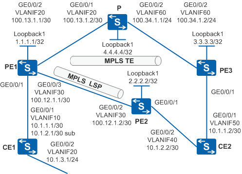
The MPLS network of an ISP provides the L2VPN service to many users. The users connect to the MPLS network through PE1, PE2, and PE3, and new sites will be added in the future. A proper VPN solution is required to provide secure VPN services for users and to simplify configuration when new users connect to the network. In addition, this solution must ensure highly stable communication between CE1 and CE2.
Martini VLL FRR, as shown in Figure 1, satisfies these requirements.

In this scenario, to avoid loops, ensure that all connected interfaces have STP disabled and connected interfaces are removed from VLAN 1. If STP is enabled and VLANIF interfaces of switches are used to construct a Layer 3 ring network, an interface on the network will be blocked. As a result, Layer 3 services on the network cannot run normally.
By default, LNP is enabled globally on the device. If a VLANIF interface is used as an AC-side interface for L2VPN, the configuration conflicts with LNP. In this case, run the lnp disable command in the system view to disable LNP.
The lnp disable command has no impact on services before the device restarts. After the device restarts, the device can only forward packets from the VLANs specified by the port default vlan command at Layer 2. The port default vlan 1 command is configured by default, so only packets of VLAN 1 can be forwarded at Layer 2.
Configuration Roadmap
VLL FRR can be configured to ensure highly stable communication between CE1 and CE2. If only a small number of new sites will be added in the future, Martini VLL FRR can be configured.
The configuration roadmap is as follows:
Configure OSPF on the backbone network.
Set up an MPLS TE tunnel between PE1 and PE3, and an LSP tunnel between PE1 and PE2. The PW between PE1 and PE3 is the primary PW and uses the MPLS TE tunnel.
Set up an MPLS LDP session between PE1 and PE2, and set up a remote MPLS LDP session between PE1 and PE3. The PW between PE1 and PE2 is the secondary PW and uses the MPLS LSP tunnel.
Use PW templates to configure PWs on the PEs. The primary PW uses the MPLS TE tunnel, so you need to apply a tunnel policy to the primary PW.
Set up BFD for PW sessions between PE1 and PE2, and between PE1 and PE3 to detect faults on the PWs.
Enable fault notification on the physical layer on PE2 and PE3. When BFD detects a failure of the primary PW, the AC on the primary PW connected to the dual-homed CE goes Down. Then L2VPN traffic is quickly switched to the secondary PW. When BFD detects fault recovery on the primary PW, L2VPN traffic can be switched back to the primary PW.
Procedure
- Configure VLANs that each interface belongs to and assign an IP address to each VLANIF interface according to the Figure 1.
# Configure CE1. The configuration on PE1, PE2, PE3, P and CE2 is similar to the CE1, and is not mentioned here.
<HUAWEI> system-view
[HUAWEI] sysname CE1
[CE1] vlan batch 10 20
[CE1] interface vlanif 10
[CE1-Vlanif10] ip address 10.1.1.1 255.255.255.252
[CE1-Vlanif10] ip address 10.1.2.1 255.255.255.252 sub
[CE1-Vlanif10] quit
[CE1] interface vlanif 20
[CE1-Vlanif20] ip address 10.1.3.1 255.255.255.0
[CE1-Vlanif20] quit
[CE1] interface gigabitethernet 0/0/1
[CE1-GigabitEthernet0/0/1] port link-type trunk
[CE1-GigabitEthernet0/0/1] port trunk pvid vlan 10
[CE1-GigabitEthernet0/0/1] port trunk allow-pass vlan 10
[CE1-GigabitEthernet0/0/1] quit
[CE1] interface gigabitethernet 0/0/2
[CE1-GigabitEthernet0/0/2] port link-type trunk
[CE1-GigabitEthernet0/0/2] port trunk allow-pass vlan 20
[CE1-GigabitEthernet0/0/2] quit
- Configure an IGP protocol on the MPLS backbone network so that PEs and Ps can communicate with each other.
# Configure PE1.
[PE1] interface loopback 1
[PE1-LoopBack1] ip address 1.1.1.1 32
[PE1-LoopBack1] quit
[PE1] ospf 1
[PE1-ospf-1] area 0
[PE1-ospf-1-area-0.0.0.0] network 1.1.1.1 0.0.0.0
[PE1-ospf-1-area-0.0.0.0] network 100.13.1.0 0.0.0.3
[PE1-ospf-1-area-0.0.0.0] network 100.12.1.0 0.0.0.3
[PE1-ospf-1-area-0.0.0.0] quit
[PE1-ospf-1] quit
# Configure P.
[P] interface loopback 1
[P-LoopBack1] ip address 4.4.4.4 32
[P-LoopBack1] quit
[P] ospf 1
[P-ospf-1] area 0
[P-ospf-1-area-0.0.0.0] network 100.13.1.0 0.0.0.3
[P-ospf-1-area-0.0.0.0] network 100.34.1.0 0.0.0.3
[P-ospf-1-area-0.0.0.0] network 4.4.4.4 0.0.0.0
[P-ospf-1-area-0.0.0.0] quit
[P-ospf-1] quit
# Configure PE3.
[PE3] interface loopback 1
[PE3-LoopBack1] ip address 3.3.3.3 32
[PE3-LoopBack1] quit
[PE3] ospf 1
[PE3-ospf-1] area 0
[PE3-ospf-1-area-0.0.0.0] network 3.3.3.3 0.0.0.0
[PE3-ospf-1-area-0.0.0.0] network 100.34.1.0 0.0.0.3
[PE3-ospf-1-area-0.0.0.0] quit
[PE3-ospf-1] quit
# Configure PE2.
[PE2] interface loopback 1
[PE2-LoopBack1] ip address 2.2.2.2 32
[PE2-LoopBack1] quit
[PE2] ospf 1
[PE2-ospf-1] area 0
[PE2-ospf-1-area-0.0.0.0] network 2.2.2.2 0.0.0.0
[PE2-ospf-1-area-0.0.0.0] network 100.12.1.0 0.0.0.3
[PE2-ospf-1-area-0.0.0.0] quit
[PE2-ospf-1] quit
After the configuration is complete, run the display ip routing-table command on PEs. You can see that PE1 and PE2, and PE1 and PE3 have learned the routes on Loopback1 interfaces of each other.
- Configure basic MPLS functions on the MPLS backbone network.
Enable MPLS, and specify the LSR-ID as the IP address of Loopback1 interface. Enable MPLS on interfaces connecting the backbone network.
# Configure PE1.
[PE1] mpls lsr-id 1.1.1.1
[PE1] mpls
[PE1-mpls] quit
[PE1] interface vlanif 20
[PE1-Vlanif20] mpls
[PE1-Vlanif20] quit
[PE1] interface vlanif 30
[PE1-Vlanif30] mpls
[PE1-Vlanif30] quit
The configurations of PE2, PE3, and P are similar to the configuration of PE1, and are not mentioned here.
- Set up MPLS TE tunnels between PE1 and PE3, and LSP tunnels between PE1 and PE2.
# Configure PE1.
[PE1] mpls
[PE1-mpls] mpls te
[PE1-mpls] mpls rsvp-te
[PE1-mpls] mpls te cspf
[PE1-mpls] quit
[PE1] interface vlanif 20
[PE1-Vlanif20] mpls te
[PE1-Vlanif20] mpls rsvp-te
[PE1-Vlanif20] quit
[PE1] interface tunnel 2
[PE1-Tunnel2] ip address unnumbered interface loopback1
[PE1-Tunnel2] tunnel-protocol mpls te
[PE1-Tunnel2] destination 3.3.3.3
[PE1-Tunnel2] mpls te tunnel-id 13
[PE1-Tunnel2] mpls te commit
[PE1-Tunnel2] quit
[PE1] ospf 1
[PE1-ospf-1] opaque-capability enable
[PE1-ospf-1] area 0
[PE1-ospf-1-area-0.0.0.0] mpls-te enable
[PE1-ospf-1-area-0.0.0.0] quit
[PE1-ospf-1] quit
# Configure P.
[P] mpls
[P-mpls] mpls te
[P-mpls] mpls rsvp-te
[P-mpls] quit
[P] interface vlanif 20
[P-Vlanif20] mpls te
[P-Vlanif20] mpls rsvp-te
[P-Vlanif20] quit
[P] interface vlanif 60
[P-Vlanif60] mpls te
[P-Vlanif60] mpls rsvp-te
[P-Vlanif60] quit
[P] ospf 1
[P-ospf-1] opaque-capability enable
[P-ospf-1] area 0
[P-ospf-1-area-0.0.0.0] mpls-te enable
[P-ospf-1-area-0.0.0.0] quit
[P-ospf-1] quit
# Configure PE3.
[PE3] mpls
[PE3-mpls] mpls te
[PE3-mpls] mpls rsvp-te
[PE3-mpls] mpls te cspf
[PE3-mpls] quit
[PE3] interface vlanif 60
[PE3-Vlanif60] mpls te
[PE3-Vlanif60] mpls rsvp-te
[PE3-Vlanif60] quit
[PE3] interface tunnel 2
[PE3-Tunnel2] ip address unnumbered interface LoopBack1
[PE3-Tunnel2] tunnel-protocol mpls te
[PE3-Tunnel2] destination 1.1.1.1
[PE3-Tunnel2] mpls te tunnel-id 31
[PE3-Tunnel2] mpls te commit
[PE3-Tunnel2] quit
[PE3] ospf 1
[PE3-ospf-1] opaque-capability enable
[PE3-ospf-1] area 0
[PE3-ospf-1-area-0.0.0.0] mpls-te enable
[PE3-ospf-1-area-0.0.0.0] quit
[PE3-ospf-1] quit
# Configure PE1.
[PE1] mpls ldp
[PE1-mpls-ldp] quit
[PE1] interface vlanif 30
[PE1-Vlanif30] mpls ldp
[PE1-Vlanif30] quit
# Configure PE2.
[PE2] mpls ldp
[PE2-mpls-ldp] quit
[PE2] interface vlanif 30
[PE2-Vlanif30] mpls ldp
[PE2-Vlanif30] quit
After the configuration is complete, run the display tunnel-info all command on PEs. You can see that MPLS TE tunnels are set up between PE1 and PE3, and MPLS LSP tunnels are set up between PE1 and PE2.
The display on PE1 is used as an example.
[PE1] display tunnel-info all
* -> Allocated VC Token
Tunnel ID           Type                 Destination           Token
----------------------------------------------------------------------
0x15                cr lsp                3.3.3.3                21
0x16                lsp                   2.2.2.2                22
0x17                lsp                   2.2.2.2                23
0x18                lsp                   3.3.3.3                24
- Establish a remote LDP session between PEs.
# Use the loopback interface address of the LDP remote peer to establish a remote LDP session.
In this example, PE1 and PE2 are directly connected and you do not need to manually configure remote LDP sessions between them.
# Configure PE1.
[PE1] mpls ldp remote-peer 3.3.3.3
[PE1-mpls-ldp-remote-3.3.3.3] remote-ip 3.3.3.3
[PE1-mpls-ldp-remote-3.3.3.3] quit
# Configure PE3.
[PE3] mpls ldp
[PE3-mpls-ldp] quit
[PE3] mpls ldp remote-peer 1.1.1.1
[PE3-mpls-ldp-remote-1.1.1.1] remote-ip 1.1.1.1
[PE3-mpls-ldp-remote-1.1.1.1] quit
After the configuration is complete, run the display mpls ldp session command on PEs. You can see that the status of the remote LDP peer relationship is Operational, indicating that remote LDP sessions are set up.
The display on PE1 is used as an example.
[PE1] display mpls ldp session

 LDP Session(s) in Public Network
 Codes: LAM(Label Advertisement Mode), SsnAge Unit(DDDD:HH:MM)
 A '*' before a session means the session is being deleted.
 ------------------------------------------------------------------------------
 PeerID             Status      LAM  SsnRole  SsnAge      KASent/Rcv
 ------------------------------------------------------------------------------
 2.2.2.2:0          Operational DU   Passive  000:00:03   16/16
 3.3.3.3:0          Operational DU   Passive  000:00:00   1/1
 ------------------------------------------------------------------------------
 TOTAL: 2 session(s) Found.
- Configure tunnel policies on PEs.
# Configure PE1.
[PE1] tunnel-policy p1
[PE1-tunnel-policy-p1] tunnel select-seq cr-lsp load-balance-number 1
[PE1-tunnel-policy-p1] quit
# Configure PE3.
[PE3] tunnel-policy p1
[PE3-tunnel-policy-p1] tunnel select-seq cr-lsp load-balance-number 1
[PE3-tunnel-policy-p1] quit
- Configure PWs on PEs by using PW templates.
# Configure active and standby PWs on PE1. Configure a PW on PE2 and PE3 respectively. The two PWs are both active PWs.
# Configure PE1.
[PE1] mpls l2vpn
[PE1-l2vpn] quit
[PE1] pw-template 1to2
[PE1-pw-template-1to2] peer-address 2.2.2.2
[PE1-pw-template-1to2] control-word
[PE1-pw-template-1to2] quit
[PE1] pw-template 1to3
[PE1-pw-template-1to3] peer-address 3.3.3.3
[PE1-pw-template-1to3] control-word
[PE1-pw-template-1to3] quit
[PE1] interface gigabitethernet 0/0/1
[PE1-GigabitEthernet0/0/1] undo portswitch
[PE1-GigabitEthernet0/0/1] mpls l2vc pw-template 1to3 100 tunnel-policy p1
[PE1-GigabitEthernet0/0/1] mpls l2vc pw-template 1to2 200 secondary
[PE1-GigabitEthernet0/0/1] quit
# Configure PE2.
[PE2] mpls l2vpn
[PE2-l2vpn] quit
[PE2] pw-template 2to1
[PE2-pw-template-2to1] peer-address 1.1.1.1
[PE2-pw-template-2to1] control-word
[PE2-pw-template-2to1] quit
[PE2] interface gigabitethernet 0/0/1
[PE2-GigabitEthernet0/0/1] undo portswitch
[PE2-GigabitEthernet0/0/1] mpls l2vc pw-template 2to1 200
[PE2-GigabitEthernet0/0/1] quit
# Configure PE3.
[PE3] mpls l2vpn
[PE3-l2vpn] quit
[PE3] pw-template 3to1
[PE3-pw-template-3to1] peer-address 1.1.1.1
[PE3-pw-template-3to1] control-word
[PE3-pw-template-3to1] quit
[PE3] interface gigabitethernet 0/0/1
[PE3-GigabitEthernet0/0/1] undo portswitch
[PE3-GigabitEthernet0/0/1] mpls l2vc pw-template 3to1 100 tunnel-policy p1
[PE3-GigabitEthernet0/0/1] quit
After the configuration is complete, view information about L2VPN connections on PEs. Run the display mpls l2vc command on PEs. You can see that the active and standby PWs are established and the PW status is Up. The active PW is Active, and the standby PW is InActive.
The display on PE1 is used as an example.
[PE1] display mpls l2vc interface gigabitethernet 0/0/1
 *client interface       : GigabitEthernet0/0/1 is up
  Administrator PW       : no
  session state          : up
  AC status              : up
  Ignore AC state        : disable
  VC state               : up
  Label state            : 0
  Token state            : 0
  VC ID                  : 100
  VC type                : Ethernet
  destination            : 3.3.3.3
  local group ID         : 0            remote group ID      : 0
  local VC label         : 4097         remote VC label      : 4096
  local AC OAM State     : up
  local PSN OAM State    : up
  local forwarding state : forwarding
  local status code      : 0x0
  remote AC OAM state    : up
  remote PSN OAM state   : up
  remote forwarding state: forwarding
  remote status code     : 0x0
  ignore standby state   : no
  BFD for PW             : unavailable
  VCCV State             : up
  manual fault           : not set
  active state           : active
  forwarding entry       : exist
  link state             : up
  local VC MTU           : 1500         remote VC MTU        : 1500
  local VCCV             : cw alert ttl lsp-ping bfd
  remote VCCV            : cw alert ttl lsp-ping bfd
  local control word     : enable       remote control word  : enable
  tunnel policy name     : p1
  PW template name       : 1to3
  primary or secondary   : primary
  load balance type      : flow
  Access-port            : false
  Switchover Flag        : false
  VC tunnel/token info   : 1 tunnels/tokens
    NO.0  TNL type       : cr lsp, TNL ID : 0x15
    Backup TNL type      : lsp   , TNL ID : 0x0
  create time            : 0 days, 0 hours, 1 minutes, 4 seconds
  up time                : 0 days, 0 hours, 0 minutes, 57 seconds
  last change time       : 0 days, 0 hours, 0 minutes, 57 seconds
  VC last up time        : 2014/12/23 18:49:30
  VC total up time       : 0 days, 0 hours, 0 minutes, 57 seconds
  CKey                   : 2
  NKey                   : 1
  PW redundancy mode     : frr
  AdminPw interface      : --
  AdminPw link state     : --
  Diffserv Mode          : uniform
  Service Class          : be
  Color                  : --
  DomainId               : --
  Domain Name            : --

 *client interface       : GigabitEthernet0/0/1 is up
  Administrator PW       : no
  session state          : up
  AC status              : up
  VC state               : up
  Label state            : 0
  Token state            : 0
  VC ID                  : 200
  VC type                : Ethernet
  destination            : 2.2.2.2
  local group ID         : 0            remote group ID      : 0
  local VC label         : 4098         remote VC label      : 4097
  local AC OAM State     : up
  local PSN OAM State    : up
  local forwarding state : forwarding
  local status code      : 0x0
  remote AC OAM state    : up
  remote PSN OAM state   : up
  remote forwarding state: forwarding
  remote status code     : 0x0
  ignore standby state   : no
  BFD for PW             : unavailable
  VCCV State             : up
  manual fault           : not set
  active state           : inactive
  forwarding entry       : exist
  link state             : up
  local VC MTU           : 1500         remote VC MTU        : 1500
  local VCCV             : cw alert ttl lsp-ping bfd
  remote VCCV            : cw alert ttl lsp-ping bfd
  local control word     : enable       remote control word  : enable
  tunnel policy name     : --
  PW template name       : 1to2
  primary or secondary   : secondary
  load balance type      : flow
  Access-port            : false
  VC tunnel/token info   : 1 tunnels/tokens
    NO.0  TNL type       : lsp   , TNL ID : 0x16
    Backup TNL type      : lsp   , TNL ID : 0x0
  create time            : 0 days, 0 hours, 1 minutes, 4 seconds
  up time                : 0 days, 0 hours, 0 minutes, 59 seconds
  last change time       : 0 days, 0 hours, 0 minutes, 59 seconds
  VC last up time        : 2014/12/23 18:49:28
  VC total up time       : 0 days, 0 hours, 0 minutes, 59 seconds
  CKey                   : 4
  NKey                   : 3
  PW redundancy mode     : frr
  AdminPw interface      : --
  AdminPw link state     : --
  Diffserv Mode          : uniform
  Service Class          : be
  Color                  : --
  DomainId               : --
  Domain Name            : --

 reroute policy          : delay 30 s, resume 10 s
 reason of last reroute  : LDP notification message was forwarded
 time of last reroute    : 0 days, 0 hours, 0 minutes, 27 seconds
 delay timer ID          : --           residual time :--
 resume timer ID         : --           residual time :--
- Configure devices to ensure network connectivity.
Configure two default routes on CE2, and assign preference to the route with Vlanif50 as the outbound interface.
# Configure CE2.
[CE2] ip route-static 0.0.0.0 0.0.0.0 vlanif50 10.1.1.1
[CE2] ip route-static 0.0.0.0 0.0.0.0 vlanif40 10.1.2.1 preference 100
- Configure BFD for PWs between PEs, and enable physical layer fault notification on PE2 and PE3.
Here, dynamic BFD for PWs is used as an example.
# Configure PE1.
[PE1] bfd
[PE1-bfd] quit
[PE1] bfd for pw enable
[PE1] interface gigabitethernet 0/0/1
[PE1-GigabitEthernet0/0/1] mpls l2vpn pw bfd min-rx-interval 100 min-tx-interval 100
[PE1-GigabitEthernet0/0/1] mpls l2vpn pw bfd min-rx-interval 100 min-tx-interval 100 secondary
[PE1-GigabitEthernet0/0/1] quit
# Configure PE2.
[PE2] bfd
[PE2-bfd] quit
[PE2] bfd for pw enable
[PE2] interface gigabitethernet 0/0/1
[PE2-GigabitEthernet0/0/1] mpls l2vpn pw bfd min-rx-interval 100 min-tx-interval 100
[PE2-GigabitEthernet0/0/1] mpls l2vpn trigger if-down
[PE2-GigabitEthernet0/0/1] quit
# Configure PE3.
[PE3] bfd
[PE3-bfd] quit
[PE3] bfd for pw enable
[PE3] interface gigabitethernet 0/0/1
[PE3-GigabitEthernet0/0/1] mpls l2vpn pw bfd min-rx-interval 100 min-tx-interval 100
[PE3-GigabitEthernet0/0/1] mpls l2vpn trigger if-down
[PE3-GigabitEthernet0/0/1] quit
After the configuration is complete, BFD sessions are set up between PE1 and PE2, and between PE1 and PE3. Run the display bfd session all command. You can see that the BFD session status is Up.
The display on PE1 is used as an example.
[PE1] display bfd session all
--------------------------------------------------------------------------------
Local  Remote PeerIpAddr       State     Type         InterfaceName
--------------------------------------------------------------------------------
8192   8192   --.--.--.--      Up        D_PW(M)      GigabitEthernet0/0/1
8193   8192   --.--.--.--      Up        D_PW(S)      GigabitEthernet0/0/1
--------------------------------------------------------------------------------
     Total UP/DOWN Session Number : 2/0
Run the display bfd configuration all command. You can view the BFD configuration, and find that the Commit field is True.
[PE1] display bfd configuration all -------------------------------------------------------------------------------- CFG Name CFG Type LocalDiscr MIndex SessNum Commit AdminDown -------------------------------------------------------------------------------- dyn_8192 Dynamic 8192 256 1 True False dyn_8193 Dynamic 8193 257 1 True False -------------------------------------------------------------------------------- Total Commit/Uncommit CFG Number : 2/0 - Verify the configuration.
# Run the display mpls l2vc interface command on PE1. If the configuration is successful, you can see that the active PW is Active, the standby PW is InActive, and BFD for PWs is available.
[PE1] display mpls l2vc interface gigabitethernet 0/0/1
 *client interface       : GigabitEthernet0/0/1 is up
  Administrator PW       : no
  session state          : up
  AC status              : up
  Ignore AC state        : disable
  VC state               : up
  Label state            : 0
  Token state            : 0
  VC ID                  : 100
  VC type                : Ethernet
  destination            : 3.3.3.3
  local group ID         : 0            remote group ID      : 0
  local VC label         : 21504        remote VC label      : 21504
  local AC OAM State     : up
  local PSN OAM State    : up
  local forwarding state : forwarding
  local status code      : 0x0
  remote AC OAM state    : up
  remote PSN OAM state   : up
  remote forwarding state: forwarding
  remote status code     : 0x0
  ignore standby state   : no
  Dynamic BFD for PW     : enable
  Detect Multipier       : 3
  Min Transit Interval   : 100
  Max Receive Interval   : 100
  Dynamic BFD Session    : built
  BFD for PW             : available
    BFD sessionIndex     : 256          BFD state : up
  VCCV State             : up
  manual fault           : not set
  active state           : active
  forwarding entry       : exist
  link state             : up
  local VC MTU           : 1500         remote VC MTU        : 1500
  local VCCV             : cw alert ttl lsp-ping bfd
  remote VCCV            : cw alert ttl lsp-ping bfd
  local control word     : enable       remote control word  : enable
  tunnel policy name     : p1
  PW template name       : 1to3
  primary or secondary   : primary
  load balance type      : flow
  Access-port            : false
  Switchover Flag        : false
  VC tunnel/token info   : 1 tunnels/tokens
    NO.0  TNL type       : cr lsp, TNL ID : 0x42002000
    Backup TNL type      : lsp   , TNL ID : 0x0
  create time            : 0 days, 1 hours, 5 minutes, 19 seconds
  up time                : 0 days, 0 hours, 43 minutes, 33 seconds
  last change time       : 0 days, 0 hours, 43 minutes, 33 seconds
  VC last up time        : 2008-07-24 12:31:31
  VC total up time       : 0 days, 2 hours, 12 minutes, 51 seconds
  CKey                   : 16
  NKey                   : 15
  PW redundancy mode     : frr
  AdminPw interface      : --
  AdminPw link state     : --
  Diffserv Mode          : uniform
  Service Class          : be
  Color                  : --
  DomainId               : --
  Domain Name            : --

 *client interface       : GigabitEthernet0/0/1 is up
  Administrator PW       : no
  session state          : up
  AC status              : up
  VC state               : up
  Label state            : 0
  Token state            : 0
  VC ID                  : 200
  VC type                : Ethernet
  destination            : 2.2.2.2
  local group ID         : 0            remote group ID      : 0
  local VC label         : 21505        remote VC label      : 21505
  local AC OAM State     : up
  local PSN OAM State    : up
  local forwarding state : forwarding
  local status code      : 0x0
  remote AC OAM state    : up
  remote PSN OAM state   : up
  remote forwarding state: forwarding
  remote status code     : 0x0
  ignore standby state   : no
  Dynamic BFD for PW     : enable
  Detect Multipier       : 3
  Min Transit Interval   : 100
  Max Receive Interval   : 100
  Dynamic BFD Session    : built
  BFD for PW             : available
    BFD sessionIndex     : 257          BFD state : up
  VCCV State             : up
  manual fault           : not set
  active state           : inactive
  forwarding entry       : exist
  link state             : up
  local VC MTU           : 1500         remote VC MTU       : 1500
  local VCCV             : cw alert ttl lsp-ping bfd
  remote VCCV            : cw alert ttl lsp-ping bfd
  local control word     : enable       remote control word  : enable
  tunnel policy name     : --
  PW template name       : 1to2
  primary or secondary   : secondary
  load balance type      : flow
  Access-port            : false
  VC tunnel/token info   : 1 tunnels/tokens
    NO.0  TNL type       : lsp   , TNL ID : 0x2002001
    Backup TNL type      : lsp   , TNL ID : 0x0
  create time            : 0 days, 1 hours, 4 minutes, 31 seconds
  up time                : 0 days, 0 hours, 43 minutes, 44 seconds
  last change time       : 0 days, 0 hours, 43 minutes, 44 seconds
  VC last up time        : 2008-07-24 12:31:31
  VC total up time       : 0 days, 2 hours, 12 minutes, 51 seconds
  CKey                   : 17
  NKey                   : 18
  PW redundancy mode     : frr
  AdminPw interface      : --
  AdminPw link state     : --
  Diffserv Mode          : uniform
  Service Class          : be
  Color                  : --
  DomainId               : --
  Domain Name            : --

 reroute policy          : delay 30 s, resume 10 s
 reason of last reroute  : LDP notification message was forwarded
 time of last reroute    : 0 days, 0 hours, 43 minutes, 2 seconds
 delay timer ID          : --           residual time :--
 resume timer ID         : --           residual time :--
# Run the display ip routing-table command on CE2. You can find that the outbound interface on CE2 for the default route is Vlanif50. This indicates that traffic is transmitted along the primary path. The display on CE2 is used as an example:
[CE2] display ip routing-table 0.0.0.0
Route Flags: R - relay, D - download to fib, T - to vpn-instance
------------------------------------------------------------------------------
Routing Table : Public
Summary Count : 1
Destination/Mask    Proto   Pre  Cost      Flags NextHop         Interface

        0.0.0.0/0   Static  60   0           D   10.1.1.1        Vlanif50
CE2 can ping address 10.1.3.1 of CE1 successfully.
# Simulate a fault on GigabitEthernet0/0/2 of PE3.
[PE3] interface gigabitethernet 0/0/2
[PE3-GigabitEthernet0/0/2] shutdown
[PE3-GigabitEthernet0/0/2] quit
# Run the display bfd session all command on PE1. You can see that the BFD session of the active PW is Down.
[PE1] display bfd session all
--------------------------------------------------------------------------------
Local Remote     PeerIpAddr      State     Type         InterfaceName
--------------------------------------------------------------------------------
8193  8192       --.--.--.--     Up        D_PW(S)      GigabitEthernet0/0/1
--------------------------------------------------------------------------------
Total UP/DOWN Session Number : 1/0
# Run the display mpls 12vc interface command on PE1. You can see that the active PW status becomes Inactive and the standby PW status becomes Active.
[PE1] display mpls l2vc interface gigabitethernet 0/0/1
 *client interface       : GigabitEthernet0/0/1 is up
  Administrator PW       : no
  session state          : down
  AC status              : up
  Ignore AC state        : disable
  VC state               : down
  Label state            : 0
  Token state            : 0
  VC ID                  : 100
  VC type                : Ethernet
  destination            : 3.3.3.3
  local group ID         : 0            remote group ID      : 0
  local VC label         : 21504        remote VC label      : 0
  local AC OAM State     : up
  local PSN OAM State    : up
  local forwarding state : not forwarding
  local status code      : 0x1
  Dynamic BFD for PW     : enable
  Detect Multipier       : 3
  Min Transit Interval   : 100
  Max Receive Interval   : 100
  Dynamic BFD Session    : not built
  BFD for PW             : unavailable
  VCCV State             : up
  manual fault           : not set
  active state           : inactive
  forwarding entry       : not exist
  link state             : down
  local VC MTU           : 1500         remote VC MTU        : 0
  local VCCV             : cw alert ttl lsp-ping bfd
  remote VCCV            : none
  local control word     : enable       remote control word  : none
  tunnel policy name     : p1
  PW template name       : 1to3
  primary or secondary   : primary
  load balance type      : flow
  Access-port            : false
  Switchover Flag        : false
  VC tunnel/token info   : 0 tunnels/tokens
    Backup TNL type      : lsp   , TNL ID : 0x0
  create time            : 0 days, 1 hours, 5 minutes, 19 seconds
  up time                : 0 days, 0 hours, 43 minutes, 33 seconds
  last change time       : 0 days, 0 hours, 43 minutes, 33 seconds
  VC last up time        : 2008-07-24 12:31:31
  VC total up time       : 0 days, 2 hours, 12 minutes, 51 seconds
  CKey                   : 16
  NKey                   : 15
  PW redundancy mode     : frr
  AdminPw interface      : --
  AdminPw link state     : --
  Diffserv Mode          : uniform
  Service Class          : be
  Color                  : --
  DomainId               : --
  Domain Name            : --

 *client interface       : GigabitEthernet0/0/1 is up
  Administrator PW       : no
  session state          : up
  AC status              : up
  VC state               : up
  Label state            : 0
  Token state            : 0
  VC ID                  : 200
  VC type                : Ethernet
  destination            : 2.2.2.2
  local group ID         : 0            remote group ID      : 0
  local VC label         : 21505        remote VC label      : 21505
  local AC OAM State     : up
  local PSN OAM State    : up
  local forwarding state : forwarding
  local status code      : 0x0
  remote AC OAM state    : up
  remote PSN OAM state   : up
  remote forwarding state: forwarding
  remote status code     : 0x0
  ignore standby state   : no
  Dynamic BFD for PW     : enable
  Detect Multipier       : 3
  Min Transit Interval   : 100
  Max Receive Interval   : 100
  Dynamic BFD Session    : built
  BFD for PW             : available
    BFD sessionIndex     : 257          BFD state : up
  VCCV State             : up
  manual fault           : not set
  active state           : active
  forwarding entry       : exist
  link state             : up
  local VC MTU           : 1500         remote VC MTU        : 1500
  local VCCV             : cw alert ttl lsp-ping bfd
  remote VCCV            : cw alert ttl lsp-ping bfd
  local control word     : enable       remote control word  : enable
  tunnel policy name     : --
  PW template name       : 1to2
  primary or secondary   : secondary
  load balance type      : flow
  Access-port            : false
  VC tunnel/token info   : 1 tunnels/tokens
    NO.0  TNL type       : lsp   , TNL ID : 0x2002001
    Backup TNL type      : lsp   , TNL ID : 0x0
  create time            : 0 days, 1 hours, 4 minutes, 31 seconds
  up time                : 0 days, 0 hours, 43 minutes, 44 seconds
  last change time       : 0 days, 0 hours, 43 minutes, 44 seconds
  VC last up time        : 2008-07-24 12:31:31
  VC total up time       : 0 days, 2 hours, 12 minutes, 51 seconds
  CKey                   : 17
  NKey                   : 18
  PW redundancy mode     : frr
  AdminPw interface      : --
  AdminPw link state     : --
  Diffserv Mode          : uniform
  Service Class          : be
  Color                  : --
  DomainId               : --
  Domain Name            : --

 reroute policy          : delay 30 s, resume 10 s
 reason of last reroute  : LDP notification message was forwarded
 time of last reroute    : 0 days, 0 hours, 43 minutes, 2 seconds
 delay timer ID          : --           residual time :--
 resume timer ID         : --           residual time :--
# Check the routing table on CE2. You can find that the outbound interface of the default route has changed to Vlanif40. This indicates that L2VPN traffic has been switched to the secondary path.
[CE2] display ip routing-table 0.0.0.0
Route Flags: R - relay, D - download to fib, T - to vpn-instance
------------------------------------------------------------------------------
Routing Table : Public
Summary Count : 1
Destination/Mask    Proto   Pre  Cost      Flags NextHop         Interface

        0.0.0.0/0   Static  100  0           D   10.1.2.1        Vlanif40
# Remove the fault from GigabitEthernet0/0/2 of PE3.
[PE3] interface gigabitethernet 0/0/2
[PE3-GigabitEthernet0/0/2] undo shutdown
[PE3-GigabitEthernet0/0/2] quit
# After the network becomes stable, check the routing table on CE2. You can find that the outbound interface of the default route has changed to Vlanif50. This indicates that L2VPN traffic has been switched back to the primary path.
[CE2] display ip routing-table 0.0.0.0
Route Flags: R - relay, D - download to fib, T - to vpn-instance
------------------------------------------------------------------------------
Routing Table : Public
Summary Count : 1
Destination/Mask    Proto   Pre  Cost      Flags NextHop         Interface

        0.0.0.0/0   Static  60   0           D   10.1.1.1        Vlanif50
Configuration Files
-
#
sysname CE1
#
vlan batch 10 20
#
interface Vlanif10
 ip address 10.1.1.1 255.255.255.252
 ip address 10.1.2.1 255.255.255.252 sub
#
interface Vlanif20
 ip address 10.1.3.1 255.255.255.0
#
interface GigabitEthernet0/0/1
 port link-type trunk
 port trunk pvid vlan 10
 port trunk allow-pass vlan 10
#
interface GigabitEthernet0/0/2
 port link-type trunk
 port trunk allow-pass vlan 20
#
return
-
#
sysname CE2
#
vlan batch 40 50
#
interface Vlanif40
 ip address 10.1.2.2 255.255.255.252
#
interface Vlanif50
 ip address 10.1.1.2 255.255.255.252
#
interface GigabitEthernet0/0/1
 port link-type trunk
 port trunk pvid vlan 50
 port trunk allow-pass vlan 50
#
interface GigabitEthernet0/0/2
 port link-type trunk
 port trunk pvid vlan 40
 port trunk allow-pass vlan 40
#
ip route-static 0.0.0.0 0.0.0.0 Vlanif50 10.1.1.1
ip route-static 0.0.0.0 0.0.0.0 Vlanif40 10.1.2.1 preference 100
#
return
-
#
sysname PE1
#
vlan batch 20 30
#
bfd for pw enable
#
bfd
#
mpls lsr-id 1.1.1.1
mpls
 mpls te
 mpls rsvp-te
 mpls te cspf
#
mpls l2vpn
#
pw-template 1to2
 peer-address 2.2.2.2
 control-word
#
pw-template 1to3
 peer-address 3.3.3.3
 control-word
#
mpls ldp
#
mpls ldp remote-peer 3.3.3.3
 remote-ip 3.3.3.3
#
interface Vlanif20
 ip address 100.13.1.1 255.255.255.252
 mpls
 mpls te
 mpls rsvp-te
#
interface Vlanif30
 ip address 100.12.1.1 255.255.255.252
 mpls
 mpls ldp
#
interface GigabitEthernet0/0/1
 undo portswitch
 mpls l2vc pw-template 1to3 100 tunnel-policy p1
 mpls l2vpn pw bfd min-rx-interval 100 min-tx-interval 100
 mpls l2vc pw-template 1to2 200 secondary
 mpls l2vpn pw bfd min-rx-interval 100 min-tx-interval 100 secondary
#
interface GigabitEthernet0/0/2
 port link-type trunk
 port trunk allow-pass vlan 20
#
interface GigabitEthernet0/0/3
 port link-type trunk
 port trunk allow-pass vlan 30
#
interface LoopBack1
 ip address 1.1.1.1 255.255.255.255
#
interface Tunnel2
 ip address unnumbered interface LoopBack1
 tunnel-protocol mpls te
 destination 3.3.3.3
 mpls te tunnel-id 13
 mpls te commit
#
ospf 1
 opaque-capability enable
 area 0.0.0.0
  network 1.1.1.1 0.0.0.0
  network 100.12.1.0 0.0.0.3
  network 100.13.1.0 0.0.0.3
  mpls-te enable
#
tunnel-policy p1
 tunnel select-seq cr-lsp load-balance-number 1
#
return
-
#
sysname P
#
vlan batch 20 60
#
mpls lsr-id 4.4.4.4
mpls
 mpls te
 mpls rsvp-te
#
interface Vlanif20
 ip address 100.13.1.2 255.255.255.252
 mpls
 mpls te
 mpls rsvp-te
#
interface Vlanif60
 ip address 100.34.1.1 255.255.255.252
 mpls
 mpls te
 mpls rsvp-te
#
interface GigabitEthernet0/0/1
 port link-type trunk
 port trunk allow-pass vlan 20
#
interface GigabitEthernet0/0/2
 port link-type trunk
 port trunk allow-pass vlan 60
#
interface LoopBack1
 ip address 4.4.4.4 255.255.255.255
#
ospf 1
 opaque-capability enable
 area 0.0.0.0
  network 4.4.4.4 0.0.0.0
  network 100.13.1.0 0.0.0.3
  network 100.34.1.0 0.0.0.3
  mpls-te enable
#
return
-
#
sysname PE3
#
vlan batch 60
#
bfd for pw enable
#
bfd
#
mpls lsr-id 3.3.3.3
mpls
 mpls te
 mpls rsvp-te
 mpls te cspf
#
mpls l2vpn
#
pw-template 3to1
 peer-address 1.1.1.1
 control-word
#
mpls ldp
#
mpls ldp remote-peer 1.1.1.1
 remote-ip 1.1.1.1
#
interface Vlanif60
 ip address 100.34.1.2 255.255.255.252
 mpls
 mpls te
 mpls rsvp-te
#
interface GigabitEthernet0/0/1
 undo portswitch
 mpls l2vc pw-template 3to1 100 tunnel-policy p1
 mpls l2vpn pw bfd min-rx-interval 100 min-tx-interval 100
 mpls l2vpn trigger if-down
#
interface GigabitEthernet0/0/2
 port link-type trunk
 port trunk allow-pass vlan 60
#
interface LoopBack1
 ip address 3.3.3.3 255.255.255.255
#
interface Tunnel2
 ip address unnumbered interface LoopBack1
 tunnel-protocol mpls te
 destination 1.1.1.1
 mpls te tunnel-id 31
 mpls te commit
#
ospf 1
 opaque-capability enable
 area 0.0.0.0
  network 3.3.3.3 0.0.0.0
  network 100.34.1.0 0.0.0.3
  mpls-te enable
#
tunnel-policy p1
 tunnel select-seq cr-lsp load-balance-number 1
#
return
-
#
sysname PE2
#
vlan batch 30
#
bfd for pw enable
#
bfd
#
mpls lsr-id 2.2.2.2
mpls
#
mpls l2vpn
#
pw-template 2to1
 peer-address 1.1.1.1
 control-word
#
mpls ldp
#
interface Vlanif30
 ip address 100.12.1.2 255.255.255.252
 mpls
 mpls ldp
#
interface GigabitEthernet0/0/1
 undo portswitch
 mpls l2vc pw-template 2to1 200
 mpls l2vpn pw bfd min-rx-interval 100 min-tx-interval 100
 mpls l2vpn trigger if-down
#
interface GigabitEthernet0/0/2
 port link-type trunk
 port trunk allow-pass vlan 30
#
interface LoopBack1
 ip address 2.2.2.2 255.255.255.255
#
ospf 1
 area 0.0.0.0
  network 2.2.2.2 0.0.0.0
  network 100.12.1.0 0.0.0.3
#
return