Example for Configuring Inter-AS Kompella VLL (Option A)
Networking Requirements
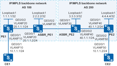
The MPLS network of an ISP provides the L2VPN service for many users. PE1 belongs to AS 100 and PE2 belongs to AS 200, as shown in Figure 1. The users connect to the MPLS network through PE1 and PE2, and new users will connect to the PEs in the future. VPN resources must be reserved for new users. A proper VPN solution is required to provide secure VPN services for users and to simplify the configuration when new users connect to the network.

By default, LNP is enabled globally on the device. If a VLANIF interface is used as an AC-side interface for L2VPN, the configuration conflicts with LNP. In this case, run the lnp disable command in the system view to disable LNP.
The lnp disable command has no impact on services before the device restarts. After the device restarts, the device can only forward packets from the VLANs specified by the port default vlan command at Layer 2. The port default vlan 1 command is configured by default, so only packets of VLAN 1 can be forwarded at Layer 2.
Configuration Roadmap
The PEs connect to different ASs (AS100 and AS200) of the ISP, so an inter-AS VPN solution is required. To simplify configuration when new users connect to the network and reserve VPN resources, configure Kompella VLL using inter-AS Option A.
The configuration roadmap is as follows:
Run an IGP protocol on the backbone network so that the devices in the same AS can communicate with each other.
Enable MPLS on the backbone and establish a dynamic LSP between the PE and the ASBR_PE.
Establish an IBGP adjacency between the PE and the ASBR_PE in an AS.
Set up a Kompella VLL connection between the PE and the ASBR_PE in an AS.
Procedure
- Configure VLANs that each interface belongs to and assign an IP address to each VLANIF interface according to Figure 1.
# Configure CE1. The configuration on CE2, PE1, PE2, ASBR_PE1 and ASBR_PE2 is similar to the configuration on CE1 and is not mentioned here.
<HUAWEI> system-view
[HUAWEI] sysname CE1
[CE1] vlan batch 10
[CE1] interface vlanif 10
[CE1-Vlanif10] ip address 10.1.1.1 255.255.255.0
[CE1-Vlanif10] quit
[CE1] interface gigabitethernet 0/0/1
[CE1-GigabitEthernet0/0/1] port link-type trunk
[CE1-GigabitEthernet0/0/1] port trunk allow-pass vlan 10
[CE1-GigabitEthernet0/0/1] quit
- Configure an IGP protocol on the backbone network.
PEs and ASBR_PEs on the MPLS backbone network can communicate with each other by using IGP. OSPF is used as the IGP protocol in this example.
# Configure PE1. The configuration on PE2, ASBR_PE1 and ASBR_PE2 is similar to the configuration on PE1 and is not mentioned here.
[PE1] interface loopback 1
[PE1-LoopBack1] ip address 1.1.1.1 32
[PE1-LoopBack1] quit
[PE1] ospf 1
[PE1-ospf-1] area 0
[PE1-ospf-1-area-0.0.0.0] network 20.1.1.0 0.0.0.255
[PE1-ospf-1-area-0.0.0.0] network 1.1.1.1 0.0.0.0
[PE1-ospf-1-area-0.0.0.0] quit
[PE1-ospf-1] quit
The configuration procedure of other devices is not mentioned. Note that the address of Loopback1 must be advertised to the IBGP peer.
After the configuration is complete, the ASBR_PE and the PEs in the same AS can learn the Loopback1 addresses of each other. Run the display ip routing-table command, and you can see that the ASBR and the PEs in the same AS can learn the Loopback1 addresses of each other.
The command output of PE1 is used as an example.
[PE1] display ip routing-table
Route Flags: R - relay, D - download to fib, T - to vpn-instance
------------------------------------------------------------------------------
Routing Tables: Public
         Destinations : 6        Routes : 6

Destination/Mask    Proto  Pre  Cost     Flags NextHop         Interface

       1.1.1.1/32    Direct 0    0          D  127.0.0.1       LoopBack1
       2.2.2.2/32   OSPF   10   1          D  20.1.1.2        Vlanif20
      20.1.1.0/24    Direct 0    0          D  20.1.1.1        Vlanif20
      20.1.1.1/32    Direct 0    0          D  127.0.0.1       Vlanif20
      127.0.0.0/8    Direct 0    0          D  127.0.0.1       InLoopBack0
     127.0.0.1/32    Direct 0    0          D  127.0.0.1       InLoopBack0
The ASBR_PE and the PEs in the same AS can ping each other's Loopback1 address.
[PE1] ping 2.2.2.2 PING 2.2.2.2: 56 data bytes, press CTRL_C to break Reply from 2.2.2.2: bytes=56 Sequence=1 ttl=255 time=90 ms Reply from 2.2.2.2: bytes=56 Sequence=2 ttl=255 time=90 ms Reply from 2.2.2.2: bytes=56 Sequence=3 ttl=255 time=60 ms Reply from 2.2.2.2: bytes=56 Sequence=4 ttl=255 time=90 ms Reply from 2.2.2.2: bytes=56 Sequence=5 ttl=255 time=60 ms --- 2.2.2.2 ping statistics --- 5 packet(s) transmitted 5 packet(s) received 0.00% packet loss round-trip min/avg/max = 60/78/90 ms - Enable MPLS and establish LSPs.
Enable MPLS and establish LDP LSPs on the ASBR_PE and the PE in the same AS.
# Configure PE1. The configuration on PE2, ASBR_PE1 and ASBR_PE2 is similar to the configuration on PE1 and is not mentioned here.
[PE1] mpls lsr-id 1.1.1.1
[PE1] mpls
[PE1-mpls] quit
[PE1] mpls ldp
[PE1-mpls-ldp] quit
[PE1] interface vlanif 20
[PE1-Vlanif20] mpls
[PE1-Vlanif20] mpls ldp
[PE1-Vlanif20] quit
After the configuration is complete, the LDP adjacencies are established between the PE and the ASBR_PEs in the same AS. Run the display mpls ldp session command on each device, and you can find that the status is Operational.
The command output of PE1 is used as an example.
[PE1] display mpls ldp session

 LDP Session(s) in Public Network
 Codes: LAM(Label Advertisement Mode), SsnAge Unit(DDDD:HH:MM)
 A '*' before a session means the session is being deleted.
 ------------------------------------------------------------------------------
 PeerID             Status      LAM  SsnRole  SsnAge      KASent/Rcv
 ------------------------------------------------------------------------------
 2.2.2.2:0         Operational DU   Passive  0000:01:03  2/2
 ------------------------------------------------------------------------------
 TOTAL: 1 session(s) Found.
- Configure IBGP.
Configure MP-IBGP connections between PE1 and ASBR_PE1, and between PE2 and ASBR_PE2.
# Configure PE1.
[PE1] bgp 100
[PE1-bgp] peer 2.2.2.2 as-number 100
[PE1-bgp] peer 2.2.2.2 connect-interface loopBack 1
[PE1-bgp] quit
# Configure ASBR_PE1.
[ASBR_PE1] bgp 100
[ASBR_PE1-bgp] peer 1.1.1.1 as-number 100
[ASBR_PE1-bgp] peer 1.1.1.1 connect-interface loopback 1
[ASBR_PE1-bgp] quit
# Configure ASBR_PE2.
[ASBR_PE2] bgp 200
[ASBR_PE2-bgp] peer 4.4.4.4 as-number 200
[ASBR_PE2-bgp] peer 4.4.4.4 connect-interface loopback 1
[ASBR_PE2-bgp] quit
# Configure PE2.
[PE2] bgp 200
[PE2-bgp] peer 3.3.3.3 as-number 200
[PE2-bgp] peer 3.3.3.3 connect-interface loopback 1
[PE2-bgp] quit
After the configuration is complete, run the display bgp peer command. The command output shows that the IBGP peer relationship between PE1 and the ASBR_PE in the same AS is Established. The command output of PE1 is used as an example.
[PE1] display bgp peer

 BGP local router ID : 1.1.1.1
 Local AS number : 100
 Total number of peers : 1                 Peers in established state : 1

  Peer            V    AS  MsgRcvd  MsgSent  OutQ Up/Down       State   PrefRcv

2.2.2.2         4   100        2        3     0  00:00:03 Established       0
- Enable BGP peers in the BGP L2VPN address family view.
After BGP peers are enabled on the PEs and ASBR_PEs in the BGP L2VPN address family view, L2VPN instance information can be exchanged between the PEs and ASBR_PEs.
# Configure PE1.
[PE1] bgp 100
[PE1-bgp] l2vpn-family
[PE1-bgp-af-l2vpn] peer 2.2.2.2 enable
[PE1-bgp-af-l2vpn] quit
[PE1-bgp] quit
# Configure ASBR_PE1.
[ASBR_PE1] bgp 100
[ASBR_PE1-bgp] l2vpn-family
[ASBR_PE1-bgp-af-l2vpn] peer 1.1.1.1 enable
[ASBR_PE1-bgp-af-l2vpn] quit
[ASBR_PE1-bgp] quit
# Configure ASBR_PE2.
[ASBR_PE2] bgp 200
[ASBR_PE2-bgp] l2vpn-family
[ASBR_PE2-bgp-af-l2vpn] peer 4.4.4.4 enable
[ASBR_PE2-bgp-af-l2vpn] quit
[ASBR_PE2-bgp] quit
# Configure PE2.
[PE2] bgp 200
[PE2-bgp] l2vpn-family
[PE2-bgp-af-l2vpn] peer 3.3.3.3 enable
[PE2-bgp-af-l2vpn] quit
[PE2-bgp] quit
- Set up the Kompella L2VPN connection between PEs.
The steps are as follows:
Enable MPLS L2VPN on the PEs and ASBR_PEs.
Create VPN instances and CE connections on PE1 and PE2.
Configure IP addresses in the same network segment for the interfaces through which CE1 and CE2 access the PEs.
# Configure PE1.In this example, a VLANIF interface is used as the AC-side interface, so you need to run the lnp disable command in the system view before performing the following steps. If you cannot disable LNP on the live network, do not use a VLANIF interface as the AC-side interface.
[PE1] mpls l2vpn
[PE1-l2vpn] quit
[PE1] mpls l2vpn vpn1 encapsulation vlan
[PE1-mpls-l2vpn-vpn1] route-distinguisher 100:1
[PE1-mpls-l2vpn-vpn1] mtu 1500
[PE1-mpls-l2vpn-vpn1] vpn-target 1:1 both
[PE1-mpls-l2vpn-vpn1] ce ce1 id 1 range 10 default-offset 0
[PE1-mpls-l2vpn-ce-vpn1-ce1] connection ce-offset 2 interface vlanif 10
[PE1-mpls-l2vpn-ce-vpn1-ce1] quit
[PE1-mpls-l2vpn-vpn1] quit
# Configure ASBR_PE1.In this example, a VLANIF interface is used as the AC-side interface, so you need to run the lnp disable command in the system view before performing the following steps. If you cannot disable LNP on the live network, do not use a VLANIF interface as the AC-side interface.
[ASBR_PE1] mpls l2vpn
[ASBR_PE1-l2vpn] quit
[ASBR_PE1] mpls l2vpn vpn1 encapsulation vlan
[ASBR_PE1-mpls-l2vpn-vpn1] route-distinguisher 100:2
[ASBR_PE1-mpls-l2vpn-vpn1] mtu 1500
[ASBR_PE1-mpls-l2vpn-vpn1] vpn-target 1:1 both
[ASBR_PE1-mpls-l2vpn-vpn1] ce ce2 id 2 range 10 default-offset 0
[ASBR_PE1-mpls-l2vpn-ce-vpn1-ce2] connection ce-offset 1 interface vlanif 30
[ASBR_PE1-mpls-l2vpn-ce-vpn1-ce2] quit
[ASBR_PE1-mpls-l2vpn-vpn1] quit
# Configure ASBR_PE2.In this example, a VLANIF interface is used as the AC-side interface, so you need to run the lnp disable command in the system view before performing the following steps. If you cannot disable LNP on the live network, do not use a VLANIF interface as the AC-side interface.
[ASBR_PE2] mpls l2vpn
[ASBR_PE2-l2vpn] quit
[ASBR_PE2] mpls l2vpn vpn1 encapsulation vlan
[ASBR_PE2-mpls-l2vpn-vpn1] route-distinguisher 200:1
[ASBR_PE2-mpls-l2vpn-vpn1] mtu 1500
[ASBR_PE2-mpls-l2vpn-vpn1] vpn-target 1:1 both
[ASBR_PE2-mpls-l2vpn-vpn1] ce ce3 id 3 range 10 default-offset 0
[ASBR_PE2-mpls-l2vpn-ce-vpn1-ce3] connection ce-offset 4 interface vlanif 30
[ASBR_PE2-mpls-l2vpn-ce-vpn1-ce3] quit
[ASBR_PE2-mpls-l2vpn-vpn1] quit
# Configure PE2.In this example, a VLANIF interface is used as the AC-side interface, so you need to run the lnp disable command in the system view before performing the following steps. If you cannot disable LNP on the live network, do not use a VLANIF interface as the AC-side interface.
[PE2] mpls l2vpn
[PE2-l2vpn] quit
[PE2] mpls l2vpn vpn1 encapsulation vlan
[PE2-mpls-l2vpn-vpn1] route-distinguisher 200:2
[PE2-mpls-l2vpn-vpn1] mtu 1500
[PE2-mpls-l2vpn-vpn1] vpn-target 1:1 both
[PE2-mpls-l2vpn-vpn1] ce ce4 id 4 range 10 default-offset 0
[PE2-mpls-l2vpn-ce-vpn1-ce4] connection ce-offset 3 interface vlanif 50
[PE2-mpls-l2vpn-ce-vpn1-ce4] quit
[PE2-mpls-l2vpn-vpn1] quit
# Configure CE1.
[CE1] interface vlanif 10
[CE1-Vlanif10] ip address 10.1.1.1 255.255.255.0
[CE1-Vlanif10] quit
# Configure CE2.
[CE2] interface vlanif 50
[CE2-Vlanif50] ip address 10.1.1.2 255.255.255.0
[CE2-Vlanif50] quit
- Verify the configuration.
Check information about the L2VPN connection on PE1. You can see that an L2VC is set up and the VC status is up.
The command outputs of PE1 and ASBR_PE2 are used as an example.
# The display on PE1 is as follows:
[PE1] display mpls l2vpn connection interface vlanif 10
conn-type: remote
     local vc state:             up
     remote vc state:            up
     local ce-id:                1
     local ce name:              ce1
     remote ce-id:               2
     intf(state,encap):          Vlanif10(up,vlan)
     peer id:                    2.2.2.2
     route-distinguisher:        100:2
     local vc label:             31745
     remote vc label:            35852
     tunnel policy:              default
     CKey:                       19
     NKey:                       3
     primary or secondary:       primary
     forward entry exist or not: true
     forward entry active or not:true
     manual fault set or not:    not set
     AC OAM state:               up
     BFD for PW session index:   --
     BFD for PW state:           invalid
     BFD for LSP state:          true
     Local C bit is not set
     Remote C bit is not set
     tunnel type:                lsp
     tunnel id:                  0x10002
     Slave tunnel type:          lsp
     Slave tunnel id:            0x0
# The display on ASBR_PE2 is as follows:
[ASBR_PE2] display mpls l2vpn connection interface vlanif 30
conn-type: remote
     local vc state:             up
     remote vc state:            up
     local ce-id:                3
     local ce name:              ce3
     remote ce-id:               4
     intf(state,encap):          Vlanif30(up,vlan)
     peer id:                    4.4.4.4
     route-distinguisher:        200:2
     local vc label:             31746
     remote vc label:            35853
     tunnel policy:              default
     CKey:                       19
     NKey:                       3
     primary or secondary:       primary
     forward entry exist or not: true
     forward entry active or not:true
     manual fault set or not:    not set
     AC OAM state:               up
     BFD for PW session index:   --
     BFD for PW state:           invalid
     BFD for LSP state:          true
     Local C bit is not set
     Remote C bit is not set
     tunnel type:                lsp
     tunnel id:                  0x10001
     Slave tunnel type:          lsp
     Slave tunnel id:            0x0
CE1 and CE2 can ping each other.
[CE1] ping 10.1.1.2
  PING 10.1.1.2: 56  data bytes, press CTRL_C to break
    Reply from 10.1.1.2: bytes=56 Sequence=1 ttl=255 time=125 ms
    Reply from 10.1.1.2: bytes=56 Sequence=2 ttl=255 time=125 ms
    Reply from 10.1.1.2: bytes=56 Sequence=3 ttl=255 time=94 ms
    Reply from 10.1.1.2: bytes=56 Sequence=4 ttl=255 time=125 ms
    Reply from 10.1.1.2: bytes=56 Sequence=5 ttl=255 time=125 ms

  --- 10.1.1.2 ping statistics ---
    5 packet(s) transmitted
    5 packet(s) received
    0.00% packet loss
    round-trip min/avg/max = 94/118/125 ms
Configuration Files
CE1 configuration file
#
sysname CE1
#
vlan batch 10
#
interface Vlanif10
 ip address 10.1.1.1 255.255.255.0
#
interface GigabitEthernet0/0/1
 port link-type trunk
 port trunk allow-pass vlan 10
#
return
PE1 configuration file

The lnp disable command has no impact on services before the device restarts. After the device restarts, the device can only forward packets from the VLANs specified by the port default vlan command at Layer 2. The port default vlan 1 command is configured by default, so only packets of VLAN 1 can be forwarded at Layer 2.
#
sysname PE1
#
vlan batch 10 20
#
lnp disable #mpls lsr-id 1.1.1.1
mpls
#
mpls l2vpn
#
mpls ldp
#
interface Vlanif10
#
interface Vlanif20
 ip address 20.1.1.1 255.255.255.0
 mpls
 mpls ldp
#
interface GigabitEthernet0/0/1
 port link-type trunk
 port trunk allow-pass vlan 10
#
interface GigabitEthernet0/0/2
 port link-type trunk
 port trunk allow-pass vlan 20
#
mpls l2vpn vpn1 encapsulation vlan
 route-distinguisher 100:1
 vpn-target 1:1 import-extcommunity
 vpn-target 1:1 export-extcommunity
 ce ce1 id 1 range 10 default-offset 0
  connection ce-offset 2 interface Vlanif10
#
interface LoopBack1
 ip address 1.1.1.1 255.255.255.255
#
bgp 100
 peer 2.2.2.2 as-number 100
 peer 2.2.2.2 connect-interface LoopBack1
 #
 ipv4-family unicast
  undo synchronization
  peer 2.2.2.2 enable
 #
 l2vpn-family
  policy vpn-target
  peer 2.2.2.2 enable
#
ospf 1
 area 0.0.0.0
  network 1.1.1.1 0.0.0.0
  network 20.1.1.0 0.0.0.255
#
return
ASBR_PE1 configuration file
The lnp disable command has no impact on services before the device restarts. After the device restarts, the device can only forward packets from the VLANs specified by the port default vlan command at Layer 2. The port default vlan 1 command is configured by default, so only packets of VLAN 1 can be forwarded at Layer 2.
#
sysname ASBR_PE1
#
vlan batch 20 30
#
lnp disable #mpls lsr-id 2.2.2.2
mpls
#
mpls l2vpn
#
mpls ldp
#
interface Vlanif20
 ip address 20.1.1.2 255.255.255.0
 mpls
 mpls ldp
#
interface Vlanif30
#
interface GigabitEthernet0/0/1
 port link-type trunk
 port trunk allow-pass vlan 20
#
interface GigabitEthernet0/0/2
 port link-type trunk
 port trunk allow-pass vlan 30
#
mpls l2vpn vpn1 encapsulation vlan
 route-distinguisher 100:2
 vpn-target 1:1 import-extcommunity
 vpn-target 1:1 export-extcommunity
 ce ce2 id 2 range 10 default-offset 0
  connection ce-offset 1 interface Vlanif30
#
interface LoopBack1
 ip address 2.2.2.2 255.255.255.255
#
bgp 100
 peer 1.1.1.1 as-number 100
 peer 1.1.1.1 connect-interface LoopBack1
 #
 ipv4-family unicast
  undo synchronization
  peer 1.1.1.1 enable
 #
 l2vpn-family
  policy vpn-target
  peer 1.1.1.1 enable
#
ospf 1
 area 0.0.0.0
  network 2.2.2.2 0.0.0.0
  network 20.1.1.0 0.0.0.255
#
return
ASBR_PE2 configuration file
The lnp disable command has no impact on services before the device restarts. After the device restarts, the device can only forward packets from the VLANs specified by the port default vlan command at Layer 2. The port default vlan 1 command is configured by default, so only packets of VLAN 1 can be forwarded at Layer 2.
#
sysname ASBR_PE2
#
vlan batch 30 40
#
lnp disable #mpls lsr-id 3.3.3.3
mpls
#
mpls l2vpn
#
mpls ldp
#
interface Vlanif30
#
interface Vlanif40
 ip address 40.1.1.1 255.255.255.0
 mpls
 mpls ldp
#
interface GigabitEthernet0/0/1
 port link-type trunk
 port trunk allow-pass vlan 30
#
interface GigabitEthernet0/0/2
 port link-type trunk
 port trunk allow-pass vlan 40
#
mpls l2vpn vpn1 encapsulation vlan
 route-distinguisher 200:1
 vpn-target 1:1 import-extcommunity
 vpn-target 1:1 export-extcommunity
 ce ce3 id 3 range 10 default-offset 0
  connection ce-offset 4 interface Vlanif30
#
interface LoopBack1
 ip address 3.3.3.3 255.255.255.255
#
bgp 200
 peer 4.4.4.4 as-number 200
 peer 4.4.4.4 connect-interface LoopBack1
 #
 ipv4-family unicast
  undo synchronization
  peer 4.4.4.4 enable
 #
 l2vpn-family
  policy vpn-target
  peer 4.4.4.4 enable
#
ospf 1
 area 0.0.0.0
  network 3.3.3.3 0.0.0.0
  network 40.1.1.0 0.0.0.255
#
return
PE2 configuration file
The lnp disable command has no impact on services before the device restarts. After the device restarts, the device can only forward packets from the VLANs specified by the port default vlan command at Layer 2. The port default vlan 1 command is configured by default, so only packets of VLAN 1 can be forwarded at Layer 2.
#
sysname PE2
#
vlan batch 40 50
#
lnp disable #mpls lsr-id 4.4.4.4
mpls
#
mpls l2vpn
#
mpls ldp
#
interface Vlanif40
 ip address 40.1.1.2 255.255.255.0
 mpls
 mpls ldp
#
interface Vlanif50
#
interface GigabitEthernet0/0/1
 port link-type trunk
 port trunk allow-pass vlan 40
#
interface GigabitEthernet0/0/2
 port link-type trunk
 port trunk allow-pass vlan 50
#
mpls l2vpn vpn1 encapsulation vlan
 route-distinguisher 200:2
 vpn-target 1:1 import-extcommunity
 vpn-target 1:1 export-extcommunity
 ce ce4 id 4 range 10 default-offset 0
  connection ce-offset 3 interface Vlanif50
#
interface LoopBack1
 ip address 4.4.4.4 255.255.255.255
#
bgp 200
 peer 3.3.3.3 as-number 200
 peer 3.3.3.3 connect-interface LoopBack1
 #
 ipv4-family unicast
  undo synchronization
  peer 3.3.3.3 enable
 #
 l2vpn-family
  policy vpn-target
  peer 3.3.3.3 enable
#
ospf 1
 area 0.0.0.0
  network 4.4.4.4 0.0.0.0
  network 40.1.1.0 0.0.0.255
#
return
CE2 configuration file
#
sysname CE2
#
vlan batch 50
#
interface Vlanif50
 ip address 10.1.1.2 255.255.255.0
#
interface GigabitEthernet0/0/1
 port link-type trunk
 port trunk allow-pass vlan 50
#
return