Example for Configuring BGP AD VPLS
Networking Requirements
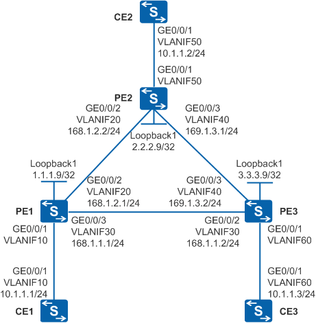
Figure 1 shows a backbone network built by an enterprise. There are a large number of branch sites on the backbone network (only three sites are shown in this example). The network environment often changes. Site1 connects to PE1 through CE1 and then connects to the backbone network. Site2 connects to PE2 through CE2 and then connects to the backbone network. Site3 connects to PE3 through CE3 and then connects to the backbone network. Users at Site1, Site2, and Site3 need to communicate at Layer 2 and user information needs to be reserved when Layer 2 packets are transmitted over the backbone network.

In this scenario, to avoid loops, ensure that all connected interfaces have STP disabled and connected interfaces are removed from VLAN 1. If STP is enabled and VLANIF interfaces of switches are used to construct a Layer 3 ring network, an interface on the network will be blocked. As a result, Layer 3 services on the network cannot run normally.
Configuration Roadmap
The configuration roadmap is as follows:
Configure transparent transmission of Layer 2 packets over the backbone network using VPLS to enable users at Site1, Site2, and Site3 to communicate at Layer 2 and reserve user information when Layer 2 packets are transmitted over the backbone network.
Use BGP AD VPLS to implement Layer 2 communication between CEs on an enterprise network with many sites and complex network environments.
Configure the IGP routing protocol on the backbone network to implement data transmission on the public network between PEs.
Configure basic MPLS functions and LDP on the backbone network to support VPLS.
Establish tunnels for transmitting data between PEs to prevent data from being known by the public network.
Enable MPLS L2VPN on PEs to implement VPLS.
Enable BGP peers to exchange VPLS information between PEs, create a VSI on each PE, specify BGP as the signaling protocol, specify the RD, VPN target, and site of the VSI, and bind AC interfaces to VSIs to implement BGP AD VPLS.
Procedure
- Configure VLANs that interfaces belong to.
Configure the VLAN that each interface belongs to and assign IP addresses to interfaces on Switch.
# Configure CE1. The configuration on PE1, PE2, PE3, CE2, and CE3 is similar to the CE1, and is not mentioned here.
<HUAWEI> system-view
[HUAWEI] sysname CE1
[CE1] vlan 10
[CE1-vlan10] quit
[CE1] interface vlanif 10
[CE1-Vlanif10] ip address 10.1.1.1 255.255.255.0
[CE1-Vlanif10] quit
[CE1] interface gigabitethernet 0/0/1
[CE1-GigabitEthernet0/0/1] port link-type trunk
[CE1-GigabitEthernet0/0/1] port trunk allow-pass vlan 10
[CE1-GigabitEthernet0/0/1] quit
Do not add AC-side physical interfaces and PW-side physical interfaces of a PE to the same VLAN; otherwise, a loop may occur.
- Configure the IGP protocol. OSPF is used in this example.
When configuring OSPF, advertise the 32-bit address of the loopback interface (LSR IDs) on PE1, PE2, and PE3.
Configure OSPF on PE1, PE2, and PE3.
# Configure PE1. The configuration on PE2 and PE3 is similar to the PE1, and is not mentioned here.
[PE1] interface loopback 1
[PE1-LoopBack1] ip address 1.1.1.9 255.255.255.255
[PE1-LoopBack1] quit
[PE1] ospf 1
[PE1-ospf-1] area 0.0.0.0
[PE1-ospf-1-area-0.0.0.0] network 1.1.1.9 0.0.0.0
[PE1-ospf-1-area-0.0.0.0] network 168.1.1.0 0.0.0.255
[PE1-ospf-1-area-0.0.0.0] network 168.1.2.0 0.0.0.255
[PE1-ospf-1-area-0.0.0.0] quit
[PE1-ospf-1] quit
After the configuration is complete, run the display ip routing-table command on PE1, PE2, and PE3. You can view the routes learned by PE1, PE2, and PE3 from each other.
- Configure basic MPLS functions and LDP.
Configure basic MPLS functions and LDP on PE1, PE2, and PE3.
# Configure PE1. The configuration on PE2 and PE3 is similar to the PE1, and is not mentioned here.
[PE1] mpls lsr-id 1.1.1.9
[PE1] mpls
[PE1-mpls] quit
[PE1] mpls ldp
[PE1-mpls-ldp] quit
[PE1] interface vlanif 20
[PE1-Vlanif20] mpls
[PE1-Vlanif20] mpls ldp
[PE1-Vlanif20] quit
[PE1] interface vlanif 30
[PE1-Vlanif30] mpls
[PE1-Vlanif30] mpls ldp
[PE1-Vlanif30] quit
After the configuration is complete, run the display mpls ldp peer command on PE1, PE2, and PE3. You can see that the peer relationship is established between each pair of PE1, PE2, and PE3. Run the display mpls ldp session command on PE1, PE2, and PE3, and you can see that an LDP session is set up between each pair of PE1, PE2, and PE3. Run the display mpls lsp command to view the LSP status.
- Enable BGP peers to exchange VPLS member information.
# Configure PE1.
[PE1] bgp 100
[PE1-bgp] peer 2.2.2.9 as-number 100
[PE1-bgp] peer 2.2.2.9 connect-interface loopback 1
[PE1-bgp] peer 3.3.3.9 as-number 100
[PE1-bgp] peer 3.3.3.9 connect-interface loopback 1
[PE1-bgp] l2vpn-ad-family
[PE1-bgp-af-l2vpn-ad] peer 2.2.2.9 enable
[PE1-bgp-af-l2vpn-ad] peer 3.3.3.9 enable
[PE1-bgp-af-l2vpn-ad] quit
[PE1-bgp] quit
# Configure PE2.
[PE2] bgp 100
[PE2-bgp] peer 1.1.1.9 as-number 100
[PE2-bgp] peer 1.1.1.9 connect-interface loopback 1
[PE2-bgp] peer 3.3.3.9 as-number 100
[PE2-bgp] peer 3.3.3.9 connect-interface loopback 1
[PE2-bgp] l2vpn-ad-family
[PE2-bgp-af-l2vpn-ad] peer 1.1.1.9 enable
[PE2-bgp-af-l2vpn-ad] peer 3.3.3.9 enable
[PE2-bgp-af-l2vpn-ad] quit
[PE2-bgp] quit
# Configure PE3.
[PE3] bgp 100
[PE3-bgp] peer 1.1.1.9 as-number 100
[PE3-bgp] peer 1.1.1.9 connect-interface loopback 1
[PE3-bgp] peer 2.2.2.9 as-number 100
[PE3-bgp] peer 2.2.2.9 connect-interface loopback 1
[PE3-bgp] l2vpn-ad-family
[PE3-bgp-af-l2vpn-ad] peer 1.1.1.9 enable
[PE3-bgp-af-l2vpn-ad] peer 2.2.2.9 enable
[PE3-bgp-af-l2vpn-ad] quit
[PE3-bgp] quit
- Enable MPLS L2VPN on PEs.
# Configure PE1.
[PE1] mpls l2vpn
[PE1-l2vpn] quit
# Configure PE2.
[PE2] mpls l2vpn
[PE2-l2vpn] quit
# Configure PE3.
[PE3] mpls l2vpn
[PE3-l2vpn] quit
- Configure VSIs on the PEs.
# Configure PE1.
[PE1] vsi vplsad1
[PE1-vsi-vplsad1] bgp-ad
[PE1-vsi-vplsad1-bgpad] vpls-id 168.1.1.1:1
[PE1-vsi-vplsad1-bgpad] vpn-target 100:1 import-extcommunity
[PE1-vsi-vplsad1-bgpad] vpn-target 100:1 export-extcommunity
[PE1-vsi-vplsad1-bgpad] quit
[PE1-vsi-vplsad1] quit
# Configure PE2.
[PE2] vsi vplsad1
[PE2-vsi-vplsad1] bgp-ad
[PE2-vsi-vplsad1-bgpad] vpls-id 168.1.1.1:1
[PE2-vsi-vplsad1-bgpad] vpn-target 100:1 import-extcommunity
[PE2-vsi-vplsad1-bgpad] vpn-target 100:1 export-extcommunity
[PE2-vsi-vplsad1-bgpad] quit
[PE2-vsi-vplsad1] quit
# Configure PE3.
[PE3] vsi vplsad1
[PE3-vsi-vplsad1] bgp-ad
[PE3-vsi-vplsad1-bgpad] vpls-id 168.1.1.1:1
[PE3-vsi-vplsad1-bgpad] vpn-target 100:1 import-extcommunity
[PE3-vsi-vplsad1-bgpad] vpn-target 100:1 export-extcommunity
[PE3-vsi-vplsad1-bgpad] quit
[PE3-vsi-vplsad1] quit
- Bind VSIs to the AC interfaces on PEs.
# Bind a VSI to VLANIF10 on PE1.
[PE1] interface vlanif 10
[PE1-Vlanif10] l2 binding vsi vplsad1
[PE1-Vlanif10] quit
# Bind a VSI to VLANIF50 on PE2.
[PE2] interface vlanif 50
[PE2-Vlanif50] l2 binding vsi vplsad1
[PE2-Vlanif50] quit
# Bind a VSI to VLANIF60 on PE3.
[PE3] interface vlanif 60
[PE3-Vlanif60] l2 binding vsi vplsad1
[PE3-Vlanif60] quit
- Verify the configuration.
# After the network becomes stable, run the display vsi name vplsad1 verbose command on PE1, and you can see that the VSI named vplsad1 has established a PW to PE2 and a PW to PE3, and the status of the VSI is Up. A PW is also established between PE2 and PE3, and the status of the VSI is Up.
[PE1] display vsi name vplsad1 verbose

 ***VSI Name               : vplsad1
    Administrator VSI      : no
    Isolate Spoken         : disable
    VSI Index              : 0
    PW Signaling           : bgpad
    Member Discovery Style : --
    PW MAC Learn Style     : unqualify
    Encapsulation Type     : vlan
    MTU                    : 1500
    Diffserv Mode          : uniform
    Mpls Exp               : --
    DomainId               : 255
    Domain Name            :
    Ignore AcState         : disable
    P2P VSI                : disable
    Create Time            : 0 days, 18 hours, 5 minutes, 30 seconds
    VSI State              : up

    VPLS ID                : 168.1.1.1:1
    RD                     : 168.1.1.1:1
    Import vpn target      : 100:1
    Export vpn target      : 100:1
    BGPAD VSI ID           : 1.1.1.9

   *Peer Router ID         : 2.2.2.9
    VPLS ID                : 168.1.1.1:1
    SAII                   : 1.1.1.9
    TAII                   : 2.2.2.9
    VC Label               : 1024
    Peer Type              : dynamic
    Session                : up
    Tunnel ID              : 0x80003f
    Broadcast Tunnel ID    : 0x80003f
    CKey                   : 2
    NKey                   : 1

   *Peer Router ID         : 3.3.3.9
    VPLS ID                : 168.1.1.1:1
    SAII                   : 1.1.1.9
    TAII                   : 3.3.3.9
    VC Label               : 1025
    Peer Type              : dynamic
    Session                : up
    Tunnel ID              : 0x800033
    Broadcast Tunnel ID    : 0x800033
    CKey                   : 4
    NKey                   : 3

    Interface Name         : Vlanif10
    State                  : up
    Access Port            : false
    Last Up Time           : 2012/07/06 15:54:46
    Total Up Time          : 0 days, 0 hours, 58 minutes, 24 seconds

   **PW Information:

   *Peer Ip Address        : 2.2.2.9
    PW State               : up
    Local VC Label         : 1024
    Remote VC Label        : 1024
    PW Type                : label
    Local  VCCV            : alert lsp-ping bfd
    Remote VCCV            : alert lsp-ping bfd
    Tunnel ID              : 0x80003f
    Broadcast Tunnel ID    : 0x80003f
    Broad BackupTunnel ID  : 0x0
    Ckey                   : 0x2
    Nkey                   : 0x1
    Main PW Token          : 0x80003f
    Slave PW Token         : 0x0
    Tnl Type               : LSP
    OutInterface           : Vlanif20
    Backup OutInterface    :
    Stp Enable             : 0
    PW Last Up Time        : 2012/07/06 16:18:23
    PW Total Up Time       : 0 days, 1 hours, 22 minutes, 13 seconds
   *Peer Ip Address        : 3.3.3.9
    PW State               : up
    Local VC Label         : 1025
    Remote VC Label        : 1025
    PW Type                : label
    Local  VCCV            : alert lsp-ping bfd
    Remote VCCV            : alert lsp-ping bfd
    Tunnel ID              : 0x800033
    Broadcast Tunnel ID    : 0x800033
    Broad BackupTunnel ID  : 0x0
    Ckey                   : 0x4
    Nkey                   : 0x3
    Main PW Token          : 0x800033
    Slave PW Token         : 0x0
    Tnl Type               : LSP
    OutInterface           : Vlanif30
    Backup OutInterface    :
    Stp Enable             : 0
    PW Last Up Time        : 2012/07/06 15:56:46
    PW Total Up Time       : 0 days, 1 hours, 0 minutes, 45 seconds
# CE1, CE2, and CE3 can ping each other. The following is an example that CE1 at 10.1.1.1 pings CE2 at 10.1.1.2.
[CE1] ping 10.1.1.2
  PING 10.1.1.2: 56  data bytes, press CTRL_C to break
    Reply from 10.1.1.2: bytes=56 Sequence=1 ttl=255 time=140 ms
    Reply from 10.1.1.2: bytes=56 Sequence=2 ttl=255 time=140 ms
    Reply from 10.1.1.2: bytes=56 Sequence=3 ttl=255 time=140 ms
    Reply from 10.1.1.2: bytes=56 Sequence=4 ttl=255 time=190 ms
    Reply from 10.1.1.2: bytes=56 Sequence=5 ttl=255 time=110 ms

  --- 10.1.1.2 ping statistics ---
    5 packet(s) transmitted
    5 packet(s) received
    0.00% packet loss
    round-trip min/avg/max = 110/144/190 ms
Configuration Files
CE1 configuration file
#
sysname CE1
#
vlan batch 10
#
interface Vlanif10
 ip address 10.1.1.1 255.255.255.0
#
interface GigabitEthernet0/0/1
 port link-type trunk
 port trunk allow-pass vlan 10
#
return
CE2 configuration file
#
sysname CE2
#
vlan batch 50
#
interface Vlanif50
 ip address 10.1.1.2 255.255.255.0
#
interface GigabitEthernet0/0/1
 port link-type trunk
 port trunk allow-pass vlan 50
#
return
CE3 configuration file
#
sysname CE3
#
vlan batch 60
#
interface Vlanif60
 ip address 10.1.1.3 255.255.255.0
#
interface GigabitEthernet0/0/1
 port link-type trunk
 port trunk allow-pass vlan 60
#
return
PE1 configuration file
#
sysname PE1
#
vlan batch 10 20 30
#
mpls lsr-id 1.1.1.9
mpls
#
mpls l2vpn
#
vsi vplsad1
 bgp-ad
  vpls-id 168.1.1.1:1
  vpn-target 100:1 import-extcommunity
  vpn-target 100:1 export-extcommunity
#
mpls ldp
#
interface Vlanif10
 l2 binding vsi vplsad1
#
interface Vlanif20
 ip address 168.1.2.1 255.255.255.0
 mpls
 mpls ldp
#
interface Vlanif30
 ip address 168.1.1.1 255.255.255.0
 mpls
 mpls ldp
#
interface GigabitEthernet0/0/1
 port link-type trunk
 port trunk allow-pass vlan 10
#
interface GigabitEthernet0/0/2
 port link-type trunk
 port trunk allow-pass vlan 20
#
interface GigabitEthernet0/0/3
 port link-type trunk
 port trunk allow-pass vlan 30
#
interface LoopBack1
 ip address 1.1.1.9 255.255.255.255
#
bgp 100
 peer 2.2.2.9 as-number 100
 peer 2.2.2.9 connect-interface LoopBack1
 peer 3.3.3.9 as-number 100
 peer 3.3.3.9 connect-interface LoopBack1
 #
 ipv4-family unicast
  undo synchronization
  peer 2.2.2.9 enable
  peer 3.3.3.9 enable
 #
 l2vpn-ad-family
  policy vpn-target
  peer 2.2.2.9 enable
  peer 3.3.3.9 enable
#
ospf 1
 area 0.0.0.0
  network 1.1.1.9 0.0.0.0
  network 168.1.1.0 0.0.0.255
  network 168.1.2.0 0.0.0.255
#
return
PE2 configuration file
#
sysname PE2
#
vlan batch 20 40 50
#
mpls lsr-id 2.2.2.9
mpls
#
mpls l2vpn
#
vsi vplsad1
 bgp-ad
  vpls-id 168.1.1.1:1
  vpn-target 100:1 import-extcommunity
  vpn-target 100:1 export-extcommunity
#
mpls ldp
#
interface Vlanif20
 ip address 168.1.2.2 255.255.255.0
 mpls
 mpls ldp
#
interface Vlanif40
 ip address 169.1.3.1 255.255.255.0
 mpls
 mpls ldp
#
interface Vlanif50
 l2 binding vsi vplsad1
#
interface GigabitEthernet0/0/1
 port link-type trunk
 port trunk allow-pass vlan 50
#
interface GigabitEthernet0/0/2
 port link-type trunk
 port trunk allow-pass vlan 20
#
interface GigabitEthernet0/0/3
 port link-type trunk
 port trunk allow-pass vlan 40
#
interface LoopBack1
 ip address 2.2.2.9 255.255.255.255
#
bgp 100
 peer 1.1.1.9 as-number 100
 peer 1.1.1.9 connect-interface LoopBack1
 peer 3.3.3.9 as-number 100
 peer 3.3.3.9 connect-interface LoopBack1
 #
 ipv4-family unicast
  undo synchronization
  peer 1.1.1.9 enable
  peer 3.3.3.9 enable
 #
 l2vpn-ad-family
  policy vpn-target
  peer 1.1.1.9 enable
  peer 3.3.3.9 enable
#
ospf 1
 area 0.0.0.0
  network 2.2.2.9 0.0.0.0
  network 168.1.2.0 0.0.0.255
  network 169.1.3.0 0.0.0.255
#
return
PE3 configuration file
#
sysname PE3
#
vlan batch 30 40 60
#
mpls lsr-id 3.3.3.9
mpls
#
mpls l2vpn
#
vsi vplsad1
 bgp-ad
  vpls-id 168.1.1.1:1
  vpn-target 100:1 import-extcommunity
  vpn-target 100:1 export-extcommunity
#
mpls ldp
#
interface Vlanif30
 ip address 168.1.1.2 255.255.255.0
 mpls
 mpls ldp
#
interface Vlanif40
 ip address 169.1.3.2 255.255.255.0
 mpls
 mpls ldp
#
interface Vlanif60
 l2 binding vsi vplsad1
#
interface GigabitEthernet0/0/1
 port link-type trunk
 port trunk allow-pass vlan 60
#
interface GigabitEthernet0/0/2
 port link-type trunk
 port trunk allow-pass vlan 30
#
interface GigabitEthernet0/0/3
 port link-type trunk
 port trunk allow-pass vlan 40
#
interface LoopBack1
 ip address 3.3.3.9 255.255.255.255
#
bgp 100
 peer 1.1.1.9 as-number 100
 peer 1.1.1.9 connect-interface LoopBack1
 peer 2.2.2.9 as-number 100
 peer 2.2.2.9 connect-interface LoopBack1
 #
 ipv4-family unicast
  undo synchronization
  peer 1.1.1.9 enable
  peer 2.2.2.9 enable
 #
 l2vpn-ad-family
  policy vpn-target
  peer 1.1.1.9 enable
  peer 2.2.2.9 enable
#
ospf 1
 area 0.0.0.0
  network 3.3.3.9 0.0.0.0
  network 168.1.1.0 0.0.0.255
  network 169.1.3.0 0.0.0.255
#
return