< Home

Example for Configuring a Local VPLS Connection

Context

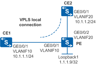
In Figure 1, sites of an enterprise at different geographical locations connect to a PE on an ISP network through CE1 and CE2. To simplify the configuration, the enterprise requires that the two CEs communicate with each other like on a LAN. In this situation, the PE functions like a Layer 2 switch to directly transmit packets without using any public network tunnel.

Figure 1 Local VPLS connection

Configuration Roadmap

  1. Configure VLANs and IP addresses for interfaces.

  2. Configure basic MPLS functions and enable MPLS L2VPN on the PE.

  3. Create a virtual switch instance (VSI) on the PE and bind the VSI to interfaces. To implement a local VPLS connection, CE1 and CE2 must be bound to the same VSI.

Procedure

  1. Configure VLANs and IP addresses for interfaces.

    # Configure CE1. The configuration of CE2 is similar to the configuration of CE1.

    <HUAWEI> system-view
    [HUAWEI] sysname CE1
    [CE1] vlan batch 10
    [CE1] interface vlanif 10
    [CE1-Vlanif10] ip address 10.1.1.1 255.255.255.0
    [CE1-Vlanif10] quit
    [CE1] interface gigabitethernet 0/0/1
    [CE1-Gigabitethernet0/0/1] port link-type trunk
    [CE1-Gigabitethernet0/0/1] port trunk allow-pass vlan 10
    [CE1-Gigabitethernet0/0/1] quit

    # Configure the PE.

    <HUAWEI> system-view
    [HUAWEI] sysname PE
    [PE] vlan batch 10 20
    [PE] interface loopback 1
    [PE-LoopBack1] ip address 1.1.1.9 255.255.255.255
    [PE-LoopBack1] quit
    [PE] interface gigabitethernet 0/0/1
    [PE-Gigabitethernet0/0/1] port link-type trunk
    [PE-Gigabitethernet0/0/1] port trunk allow-pass vlan 10
    [PE-Gigabitethernet0/0/1] quit
    [PE] interface gigabitethernet 0/0/2
    [PE-Gigabitethernet0/0/2] port link-type trunk
    [PE-Gigabitethernet0/0/2] port trunk allow-pass vlan 20
    [PE-Gigabitethernet0/0/2] quit
  2. Configure basic MPLS functions and enable MPLS L2VPN on the PE.
    [PE] mpls lsr-id 1.1.1.9
    [PE] mpls
    [PE-mpls] quit
    [PE] mpls l2vpn
    [PE-l2vpn] quit
  3. Create a VSI on the PE and bind the VSI to interfaces.

    # Create an LDP VSI.

    [PE] vsi abc static
    [PE-vsi-abc] pwsignal ldp
    [PE-vsi-abc-ldp] vsi-id 1
    [PE-vsi-abc-ldp] quit
    [PE-vsi-abc] quit

    # Bind the VSI to interfaces.

    [PE] interface vlanif 10
    [PE-Vlanif10] l2 binding vsi abc
    [PE-Vlanif10] quit
    [PE] interface vlanif 20
    [PE-Vlanif20] l2 binding vsi abc
    [PE-Vlanif20] quit
  4. Verify the configuration.

    # After the configuration is complete, run the display vsi verbose command on the PE. The command output indicates that the local VPLS connection has been set up for the VSI named abc and the VSI is in Up state.

    [PE] display vsi verbose                                                                                                          
    
     ***VSI Name               : abc                                                                                                    
        Administrator VSI      : no                                                                                                     
        Isolate Spoken         : disable                                                                                                
        VSI Index              : 0                                                                                                      
        PW Signaling           : ldp                                                                                                    
        Member Discovery Style : static                                                                                                 
        PW MAC Learn Style     : unqualify                                                                                              
        Encapsulation Type     : vlan                                                                                                   
        MTU                    : 1500                                                                                                   
        Diffserv Mode          : uniform                                                                                                
        Mpls Exp               : --                                                                                                     
        DomainId               : 255                                                                                                    
        Domain Name            :                                                                                                        
        Ignore AcState         : disable                                                                                                
        P2P VSI                : disable                                                                                                
        Create Time            : 0 days, 0 hours, 47 minutes, 48 seconds                                                                
        VSI State              : up                                                                                                     
    
        VSI ID                 : 1                                                                                                      
    
        Interface Name         : Vlanif10                                                                                               
        State                  : up                                                                                                     
        Access Port            : false                                                                                                  
        Last Up Time           : 2020/02/27 19:40:23                                                                                    
        Total Up Time          : 0 days, 0 hours, 16 minutes, 18 seconds                                                                
        Interface Name         : Vlanif20                                                                                               
        State                  : up                                                                                                     
        Access Port            : false                                                                                                  
        Last Up Time           : 2020/02/27 19:40:31                                                                                    
        Total Up Time          : 0 days, 0 hours, 16 minutes, 10 seconds

    # Ensure that CE1 can ping CE2 successfully.

    <CE1> ping 10.1.1.2                                                                                                                 
      PING 10.1.1.2: 56  data bytes, press CTRL_C to break                                                                              
        Reply from 10.1.1.2: bytes=56 Sequence=1 ttl=254 time=1 ms                                                                      
        Reply from 10.1.1.2: bytes=56 Sequence=2 ttl=254 time=1 ms                                                                      
        Reply from 10.1.1.2: bytes=56 Sequence=3 ttl=254 time=1 ms                                                                      
        Reply from 10.1.1.2: bytes=56 Sequence=4 ttl=254 time=1 ms                                                                      
        Reply from 10.1.1.2: bytes=56 Sequence=5 ttl=254 time=1 ms                                                                      
    
      --- 10.1.1.2 ping statistics ---                                                                                                  
        5 packet(s) transmitted                                                                                                         
        5 packet(s) received                                                                                                            
        0.00% packet loss                                                                                                               
        round-trip min/avg/max = 1/1/1 ms                                                                                               

Configuration Files

  • CE1 configuration file
    # 
    sysname CE1 
    # 
    vlan batch 10 
    # 
    interface Vlanif10
     ip address 10.1.1.1 255.255.255.0 
    # 
    interface GigabitEthernet0/0/1  
     port link-type trunk  
     port trunk allow-pass vlan 10 
    # 
    return
  • CE2 configuration file
    # 
    sysname CE2 
    # 
    vlan batch 20 
    # 
    interface Vlanif20
     ip address 10.1.1.2 255.255.255.0 
    # 
    interface GigabitEthernet0/0/1  
     port link-type trunk  
     port trunk allow-pass vlan 20 
    # 
    return
  • PE configuration file
    #
    sysname PE
    #
    vlan batch 10 20
    #
    mpls lsr-id 1.1.1.9
    mpls
    #
    mpls l2vpn
    #
    vsi abc static
     pwsignal ldp
      vsi-id 1
    #
    interface Vlanif10
     l2 binding vsi abc
    #
    interface Vlanif20
     l2 binding vsi abc
    #
    interface GigabitEthernet0/0/1
     port link-type trunk
     port trunk allow-pass vlan 10
    #
    interface GigabitEthernet0/0/2
     port link-type trunk
     port trunk allow-pass vlan 20
    #
    interface LoopBack1
     ip address 1.1.1.9 255.255.255.255
    #
    return
Copyright © Huawei Technologies Co., Ltd.
< Previous topic Next topic >