Example for Configuring CE Dual-Homed Kompella VPLS
Networking Requirements
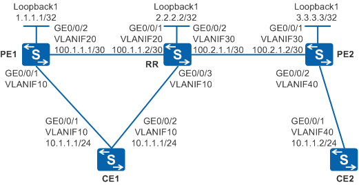
Figure 1 shows a backbone network built by an enterprise. CE1 is dual-homed to PE1 and an RR, and Site1 connects to the backbone network through CE1. Site2 connects to PE2 through CE2 and then connects to the backbone network. RR is a route reflector, and PE1 and PE2 function as clients of the RR.
Users at Site1 and Site2 need to communicate at Layer 2 and user information needs to be reserved when Layer 2 packets are transmitted over the backbone network. CE1-PE1-RR-PE2-CE2 is the active path, and CE1-RR-PE2-CE2 is the standby path.

In this scenario, to avoid loops, ensure that all connected interfaces have STP disabled and connected interfaces are removed from VLAN 1. If STP is enabled and VLANIF interfaces of switches are used to construct a Layer 3 ring network, an interface on the network will be blocked. As a result, Layer 3 services on the network cannot run normally.
Configuration Roadmap
The configuration roadmap is as follows:
Configure transparent transmission of Layer 2 packets over the backbone network using VPLS to enable users at Site1 and Site2 to communicate at Layer 2 and reserve user information when Layer 2 packets are transmitted over the backbone network.
Use CE dual-homed Kompella VPLS to implement Layer 2 communication between CEs based on enterprise network planning requirements.
Configure the IGP routing protocol on the backbone network to enable PE1, RR, and PE2 to transmit data on the public network.
Configure basic MPLS functions and LDP on the PE1, PE2, and RR to support VPLS.
Establish tunnels for transmitting data between PEs to prevent data from being known by the public network.
Enable MPLS L2VPN on PEs to implement VPLS.
Enable BGP peers to exchange VPLS information between PEs, create a VSI on each PE, establish MP IBGP peer relationship between PE1 and the RR, and between PE2 and the RR respectively, and configure router reflection on the RR to implement member discovery.
Create a VSI on each PE, specify BGP as the signaling protocol, specify the RD, VPN target, and site of the VSI, and bind AC interfaces to VSIs to implement Kompella VPLS.
Increase the multi-homed preference of the VSI on PE1 to enable BGP to preferentially select the label block of this VSI.
Procedure
- Configure VLANs that interfaces belong to.
Configure the VLAN that each interface belongs to and assign IP addresses to interfaces on Switch.
# Configure CE1. The configuration on PE1, PE2, CE2, and RR is similar to the CE1, and is not mentioned here.
<HUAWEI> system-view
[HUAWEI] sysname CE1
[CE1] vlan 10
[CE1-vlan10] quit
[CE1] interface vlanif 10
[CE1-Vlanif10] ip address 10.1.1.1 255.255.255.0
[CE1-Vlanif10] quit
[CE1] interface gigabitethernet 0/0/1
[CE1-GigabitEthernet0/0/1] port link-type trunk
[CE1-GigabitEthernet0/0/1] port trunk allow-pass vlan 10
[CE1-GigabitEthernet0/0/1] quit
[CE1] interface gigabitethernet 0/0/2
[CE1-GigabitEthernet0/0/2] port link-type trunk
[CE1-GigabitEthernet0/0/2] port trunk allow-pass vlan 10
[CE1-GigabitEthernet0/0/2] quit
Do not add AC-side physical interfaces and PW-side physical interfaces of a PE to the same VLAN; otherwise, a loop may occur.
- Configure the IGP on the backbone network.
PE1, RR, and PE2 on the backbone network can communicate using IGP. Note that IS-IS must be enabled on Loopback1.
Configure IS-IS on PE1, RR, and PE2.
# Configure PE1. The configuration on PE2 and RR is similar to the PE1, and is not mentioned here.
[PE1] isis 1
[PE1-isis-1] network-entity 10.0000.0000.0001.00
[PE1-isis-1] quit
[PE1] interface loopback 1
[PE1-LoopBack1] ip address 1.1.1.1 255.255.255.255
[PE1-LoopBack1] isis enable 1
[PE1-LoopBack1] quit
[PE1] interface vlanif 20
[PE1-Vlanif20] isis enable 1
[PE1-Vlanif20] quit
After the configuration is complete, PE1, RR, and PE2 can learn loopback addresses from each other.
The information displayed on PE1 is used as an example.
[PE1] display ip routing-table
Route Flags: R - relay, D - download to fib, T - to vpn-instance
------------------------------------------------------------------------------
Routing Tables: Public
         Destinations : 8       Routes : 8

Destination/Mask    Proto   Pre  Cost      Flags NextHop         Interface

        1.1.1.1/32  Direct  0    0           D   127.0.0.1       LoopBack1
        2.2.2.2/32  ISIS-L1 15   10          D   100.1.1.2       Vlanif20
        3.3.3.3/32  ISIS-L1 15   20          D   100.1.1.2       Vlanif20
      100.1.1.0/30  Direct  0    0           D   100.1.1.1       Vlanif20
      100.1.1.1/32  Direct  0    0           D   127.0.0.1       Vlanif20
      100.2.1.0/30  ISIS-L1 15   20          D   100.1.1.2       Vlanif20
      127.0.0.0/8   Direct  0    0           D   127.0.0.1       InLoopBack0
      127.0.0.1/32  Direct  0    0           D   127.0.0.1       InLoopBack0
PE1, RR, and PE2 can ping the Loopback1 address of each other.
- Configure basic MPLS functions and LDP.
Enable MPLS and MPLS LDP on PE1, RR, PE2, the interfaces through which PE1 is connected to RR, and the interfaces through which RR is connected to PE2 to establish LSPs.
# Configure PE1. The configuration on PE2 and RR is similar to the PE1, and is not mentioned here.
[PE1] mpls lsr-id 1.1.1.1
[PE1] mpls
[PE1-mpls] quit
[PE1] mpls ldp
[PE1-mpls-ldp] quit
[PE1] interface vlanif 20
[PE1-Vlanif20] mpls
[PE1-Vlanif20] mpls ldp
[PE1-Vlanif20] quit
After the configuration is complete, run the display mpls lsp command on each Switch. You can see that LSPs have been established between each pair of PE1, RR, and PE2.
The information displayed on PE1 is used as an example.
[PE1] display mpls lsp Flag after Out IF: (I) - LSP Is Only Iterated by RLFA ------------------------------------------------------------------------------- LSP Information: LDP LSP ------------------------------------------------------------------------------- FEC In/Out Label In/Out IF Vrf Name 1.1.1.1/32 3/NULL -/- 2.2.2.2/32 NULL/3 -/Vlanif20 2.2.2.2/32 1024/3 -/Vlanif20 3.3.3.3/32 NULL/1025 -/Vlanif20 3.3.3.3/32 1025/1025 -/Vlanif20 - Establish BGP peers and enable them to exchange VPLS information.
Establish the MP IBGP connection and enable BGP VPLS on PE1, RR, and PE2.
# Configure PE1.
[PE1] bgp 100
[PE1-bgp] peer 2.2.2.2 as-number 100
[PE1-bgp] peer 2.2.2.2 connect-interface loopback 1
[PE1-bgp] vpls-family
[PE1-bgp-af-vpls] peer 2.2.2.2 enable
[PE1-bgp-af-vpls] quit
[PE1-bgp] quit
# Configure the RR.
[RR] bgp 100
[RR-bgp] peer 1.1.1.1 as-number 100
[RR-bgp] peer 3.3.3.3 as-number 100
[RR-bgp] peer 1.1.1.1 connect-interface loopback 1
[RR-bgp] peer 3.3.3.3 connect-interface loopback 1
[RR-bgp] vpls-family
[RR-bgp-af-vpls] peer 1.1.1.1 enable
[RR-bgp-af-vpls] peer 3.3.3.3 enable
[RR-bgp-af-vpls] quit
[RR-bgp] quit
# Configure PE2.
[PE2] bgp 100
[PE2-bgp] peer 2.2.2.2 as-number 100
[PE2-bgp] peer 2.2.2.2 connect-interface loopback 1
[PE2-bgp] vpls-family
[PE2-bgp-af-vpls] peer 2.2.2.2 enable
[PE2-bgp-af-vpls] quit
[PE2-bgp] quit
After this step is complete, run the display bgp vpls peer command on the PE or RR. You can see that the status of the MP IBGP peers is Established.
- Enable the route reflection function on the RR.
# Configure the RR.
[RR] bgp 100
[RR-bgp] vpls-family
[RR-bgp-af-vpls] reflector cluster-id 100
[RR-bgp-af-vpls] peer 1.1.1.1 reflect-client
[RR-bgp-af-vpls] peer 3.3.3.3 reflect-client
[RR-bgp-af-vpls] undo policy vpn-target
[RR-bgp-af-vpls] quit
[RR-bgp] quit
- Enable MPLS L2VPN on the PE, RR, and PE2.
# Configure PE1.
[PE1] mpls l2vpn
[PE1-l2vpn] quit
# Configure the RR.
[RR] mpls l2vpn
[RR-l2vpn] quit
# Configure PE2.
[PE2] mpls l2vpn
[PE2-l2vpn] quit
- Configure VSIs on PE1, RR, and PE2 and bind the VSIs to AC interfaces.
# Configure PE1.
[PE1] vsi v1 auto
[PE1-vsi-v1] pwsignal bgp
[PE1-vsi-v1-bgp] route-distinguisher 100:1
[PE1-vsi-v1-bgp] vpn-target 1:1 import-extcommunity
[PE1-vsi-v1-bgp] vpn-target 1:1 export-extcommunity
[PE1-vsi-v1-bgp] site 1 range 5 default-offset 0
[PE1-vsi-v1-bgp] quit
[PE1-vsi-v1] quit
[PE1] interface vlanif 10
[PE1-Vlanif10] l2 binding vsi v1
[PE1-Vlanif10] quit
# Configure the RR.
[RR] vsi v1 auto
[RR-vsi-v1] pwsignal bgp
[RR-vsi-v1-bgp] route-distinguisher 100:1
[RR-vsi-v1-bgp] vpn-target 1:1 import-extcommunity
[RR-vsi-v1-bgp] vpn-target 1:1 export-extcommunity
[RR-vsi-v1-bgp] site 1 range 5 default-offset 0
[RR-vsi-v1-bgp] quit
[RR-vsi-v1] quit
[RR] interface vlanif 10
[RR-Vlanif10] l2 binding vsi v1
[RR-Vlanif10] quit
# Configure PE2.
[PE2] vsi v1 auto
[PE2-vsi-v1] pwsignal bgp
[PE2-vsi-v1-bgp] route-distinguisher 100:2
[PE2-vsi-v1-bgp] vpn-target 1:1 import-extcommunity
[PE2-vsi-v1-bgp] vpn-target 1:1 export-extcommunity
[PE2-vsi-v1-bgp] site 2 range 5 default-offset 0
[PE2-vsi-v1-bgp] quit
[PE2-vsi-v1] quit
[PE2] interface vlanif 40
[PE2-Vlanif40] l2 binding vsi v1
[PE2-Vlanif40] quit
After the configurations are complete, run the display bgp vpls all command on the PE or RR. You can see information about the local and remote label blocks of the VPLS. The RR preferentially selects the local label block.
[RR] display bgp vpls all
BGP Local Router ID : 2.2.2.2, Local AS Number : 100
Status codes : * - active, > - best
BGP.VPLS : 3 Label Blocks

--------------------------------------------------------------------------------
Route Distinguisher: 100:1
SiteID Offset NextHop         Range LabBase TunnelID   FromPeer        MHPref
--------------------------------------------------------------------------------
>  1      0      0.0.0.0         5     35840   0x0        0.0.0.0         0
1      0      1.1.1.1         5     35840   0x0        1.1.1.1         0

--------------------------------------------------------------------------------
Route Distinguisher: 100:2
SiteID Offset NextHop         Range LabBase TunnelID   FromPeer        MHPref
--------------------------------------------------------------------------------
*> 2      0      3.3.3.3         5     35840   0x0        3.3.3.3         0
- Modify the multi-homed preference of the VSI.
# Increase the multi-homed preference of the VSI on PE1 to enable BGP to preferentially select the label block advertised by PE1.
[PE1] vsi v1
[PE1-vsi-v1] multi-homing-preference 10
[PE1-vsi-v1] quit
After the configuration is complete, run the display bgp vpls all command on the RR. You can see that the RR preferentially selects the label block advertised by PE1.
[RR] display bgp vpls all
BGP Local Router ID : 2.2.2.2, Local AS Number : 100
Status codes : * - active, > - best
BGP.VPLS : 3 Label Blocks

--------------------------------------------------------------------------------
Route Distinguisher: 100:1
SiteID Offset NextHop         Range LabBase TunnelID   FromPeer        MHPref
--------------------------------------------------------------------------------
1      0      0.0.0.0         5     35840   0x0        0.0.0.0         0
*> 1      0      1.1.1.1         5     35840   0x0        1.1.1.1         10

--------------------------------------------------------------------------------
Route Distinguisher: 100:2
SiteID Offset NextHop         Range LabBase TunnelID   FromPeer        MHPref
--------------------------------------------------------------------------------
*> 2      0      3.3.3.3         5     35840   0x0        3.3.3.3         0
Run the display bgp vpls all command on PE2, and you can see that the remote label block of PE2 is advertised by PE1.
[PE2] display bgp vpls all
BGP Local Router ID : 3.3.3.3, Local AS Number : 100
Status codes : * - active, > - best
BGP.VPLS : 2 Label Blocks

--------------------------------------------------------------------------------
Route Distinguisher: 100:1
SiteID Offset NextHop         Range LabBase TunnelID   FromPeer        MHPref
--------------------------------------------------------------------------------
*> 1      0      1.1.1.1         5     35840   0x0        2.2.2.2         10

--------------------------------------------------------------------------------
Route Distinguisher: 100:2
SiteID Offset NextHop         Range LabBase TunnelID   FromPeer        MHPref
--------------------------------------------------------------------------------
>  2      0      0.0.0.0         5     35840   0x0        0.0.0.0         0
- Verify the configuration.
Run the display vpls connection bgp command on PE1 and the RR to check the VPLS connection.
You can see that the VC status on PE1 is Up.
[PE1] display vpls connection bgp verbose
VSI Name: v1                               Signaling: bgp
**Remote Site ID     : 2
VC State           : up
RD                 : 100:2
Encapsulation      : vlan
MTU                : 1500
Peer Ip Address    : 3.3.3.3
PW Type            : label
Local VC Label     : 35842
Remote VC Label    : 35841
Tunnel Policy      : --
Tunnel ID          : 0x10c
Remote Label Block : 35840/5/0
Export vpn target  : 1:1
No information is displayed on the RR.
[RR] display vpls connection bgp
PE1 is the active PE and RR is the standby PE.
Run the ping command on CEs, and you can see that CE1 and CE2 can ping each other.
[CE1] ping 10.1.1.2
  PING 10.1.1.2: 56  data bytes, press CTRL_C to break
    Reply from 10.1.1.2: bytes=56 Sequence=1 ttl=255 time=90 ms
    Reply from 10.1.1.2: bytes=56 Sequence=1 ttl=255 time=77 ms
    Reply from 10.1.1.2: bytes=56 Sequence=1 ttl=255 time=34 ms
    Reply from 10.1.1.2: bytes=56 Sequence=1 ttl=255 time=46 ms
    Reply from 10.1.1.2: bytes=56 Sequence=1 ttl=255 time=94 ms

  --- 10.1.1.2 ping statistics ---
    5 packet(s) transmitted
    5 packet(s) received
    0.00% packet loss
    round-trip min/avg/max = 34/68/94 ms
Configuration Files
CE1 configuration file
#
sysname CE1
#
vlan batch 10
#
interface Vlanif10
 ip address 10.1.1.1 255.255.255.0
#
interface GigabitEthernet0/0/1
 port link-type trunk
 port trunk allow-pass vlan 10
#
interface GigabitEthernet0/0/2
 port link-type trunk
 port trunk allow-pass vlan 10
#
return
PE1 configuration file
#
sysname PE1
#
vlan batch 10 20
#
mpls lsr-id 1.1.1.1
mpls
#
mpls l2vpn
#
vsi v1 auto
 pwsignal bgp
  route-distinguisher 100:1
  vpn-target 1:1 import-extcommunity
  vpn-target 1:1 export-extcommunity
  site 1 range 5 default-offset 0
 multi-homing-preference 10
#
mpls ldp
#
isis 1
 network-entity 10.0000.0000.0001.00
#
interface Vlanif10
 l2 binding vsi v1
#
interface Vlanif20
 ip address 100.1.1.1 255.255.255.252
 isis enable 1
 mpls
 mpls ldp
#
interface GigabitEthernet0/0/1
 port link-type trunk
 port trunk allow-pass vlan 10
#
interface GigabitEthernet0/0/2
 port link-type trunk
 port trunk allow-pass vlan 20
#
interface LoopBack1
 ip address 1.1.1.1 255.255.255.255
 isis enable 1
#
bgp 100
 peer 2.2.2.2 as-number 100
 peer 2.2.2.2 connect-interface LoopBack1
 #
 ipv4-family unicast
  undo synchronization
  peer 2.2.2.2 enable
 #
 vpls-family
  policy vpn-target
  peer 2.2.2.2 enable
#
return
RR configuration file
#
sysname RR
#
vlan batch 10 20 30
#
mpls lsr-id 2.2.2.2
mpls
#
mpls l2vpn
#
vsi v1 auto
 pwsignal bgp
  route-distinguisher 100:1
  vpn-target 1:1 import-extcommunity
  vpn-target 1:1 export-extcommunity
  site 1 range 5 default-offset 0
#
mpls ldp
#
isis 1
 network-entity 10.0000.0000.0002.00
#
interface Vlanif10
 l2 binding vsi v1
#
interface Vlanif20
 ip address 100.1.1.2 255.255.255.252
 isis enable 1
 mpls
 mpls ldp
#
interface Vlanif30
 ip address 100.2.1.1 255.255.255.252
 isis enable 1
 mpls
 mpls ldp
#
interface GigabitEthernet0/0/1
 port link-type trunk
 port trunk allow-pass vlan 20
#
interface GigabitEthernet0/0/2
 port link-type trunk
 port trunk allow-pass vlan 30
#
interface GigabitEthernet0/0/3
 port link-type trunk
 port trunk allow-pass vlan 10
#
interface LoopBack1
 ip address 2.2.2.2 255.255.255.255
 isis enable 1
#
bgp 100
peer 1.1.1.1 as-number 100
peer 1.1.1.1 connect-interface LoopBack1
peer 3.3.3.3 as-number 100
peer 3.3.3.3 connect-interface LoopBack1
#
ipv4-family unicast
undo synchronization
peer 1.1.1.1 enable
peer 3.3.3.3 enable
#
vpls-family
reflector cluster-id 100
undo policy vpn-target
peer 1.1.1.1 enable
peer 1.1.1.1 reflect-client
peer 3.3.3.3 enable
peer 3.3.3.3 reflect-client
#
return
PE2 configuration file
#
sysname PE2
#
vlan batch 30 40
#
mpls lsr-id 3.3.3.3
mpls
#
mpls l2vpn
#
vsi v1 auto
 pwsignal bgp
  route-distinguisher 100:2
  vpn-target 1:1 import-extcommunity
  vpn-target 1:1 export-extcommunity
  site 2 range 5 default-offset 0
#
mpls ldp
#
isis 1
 network-entity 10.0000.0000.0004.00
#
interface Vlanif30
 ip address 100.2.1.2 255.255.255.252
 isis enable 1
 mpls
 mpls ldp
#
interface Vlanif40
 l2 binding vsi v1
#
interface GigabitEthernet0/0/1
 port link-type trunk
 port trunk allow-pass vlan 30
#
interface GigabitEthernet0/0/2
 port link-type trunk
 port trunk allow-pass vlan 40
#
interface LoopBack1
 ip address 3.3.3.3 255.255.255.255
 isis enable 1
#
bgp 100
 peer 2.2.2.2 as-number 100
 peer 2.2.2.2 connect-interface LoopBack1
 #
 ipv4-family unicast
  undo synchronization
  peer 2.2.2.2 enable
 #
 vpls-family
  policy vpn-target
  peer 2.2.2.2 enable
#
return
CE2 configuration file
#
sysname CE2
#
vlan batch 40
#
interface Vlanif40
 ip address 10.1.1.2 255.255.255.0
#
interface GigabitEthernet0/0/1
 port link-type trunk
 port trunk allow-pass vlan 40
#
return