Example for Configuring Dynamic VLLs to Access a VPLS Network
Networking Requirements
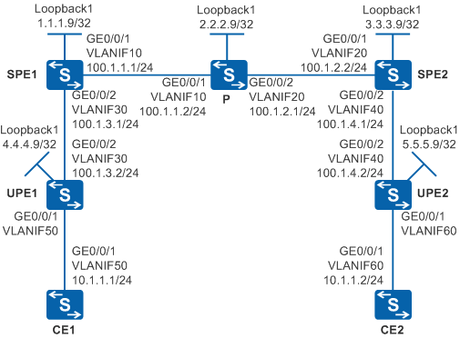
Figure 1 shows a backbone network built by an enterprise. UPEs can access SPEs through dynamic VLLs. Site1 connects to UPE1 through CE1 and then connects to the backbone network. Site2 connects to UPE2 through CE2 and then connects to the backbone network. Users at Site1 and Site2 need to communicate at Layer 2 and user information needs to be reserved when Layer 2 packets are transmitted over the backbone network.
Configuration Roadmap
The configuration roadmap is as follows:
Configure transparent transmission of Layer 2 packets over the backbone network using VPLS to enable users at Site1 and Site2 to communicate at Layer 2 and reserve user information when Layer 2 packets are transmitted over the backbone network.
Use Martini VPLS to implement Layer 2 communication between CEs based on enterprise network planning requirements.
Configure the IGP routing protocol on the UPEs, SPEs, and P to implement data transmission on the public network between PEs.
Configure basic MPLS functions and LDP on the UPEs, SPEs, and P to support VPLS.
Establish tunnels for transmitting data between PEs to prevent data from being known by the public network, including dynamic LSPs between SPEs and dynamic LSPs between UPEs and SPEs.
Enable MPLS L2VPN on PEs to implement VPLS.
Establish VLLs between UPEs and SPEs in Martini mode.
Create VSIs on SPEs, specify LDP as the signaling protocol, and bind the VSIs to AC interfaces to implement Martini VPLS.
Procedure
- Configure VLANs that interfaces belong to.
Configure the VLAN that each interface belongs to and assign IP addresses to interfaces on Switch.
# Configure CE1. The configuration on UPE1, UPE2, SPE1, SPE2, P, and CE2 is similar to the CE1, and is not mentioned here.
<HUAWEI> system-view
[HUAWEI] sysname CE1
[CE1] vlan 50
[CE1-vlan50] quit
[CE1] interface vlanif 50
[CE1-Vlanif50] ip address 10.1.1.1 255.255.255.0
[CE1-Vlanif50] quit
[CE1] interface gigabitethernet 0/0/1
[CE1-GigabitEthernet0/0/1] port link-type trunk
[CE1-GigabitEthernet0/0/1] port trunk allow-pass vlan 50
[CE1-GigabitEthernet0/0/1] quit
Configure VLANs that interfaces belong to and assign IP addresses to interfaces on other Switches by referring to Figure 1. The configuration is similar to the configuration of CE1, and is not mentioned here.

Do not add AC-side physical interfaces and PW-side physical interfaces of a PE to the same VLAN; otherwise, a loop may occur.
- Configure the IGP protocol. OSPF is used in this example.
Configure the IP address of the loopback interface on UPE1, UPE2, SPE1, SPE2, and P.
# Configure SPE1. The configuration on UPE1, UPE2, SPE2, and P is similar to the SPE1, and is not mentioned here.
[SPE1] interface loopback 1
[SPE1-LoopBack1] ip address 1.1.1.9 255.255.255.255
[SPE1-LoopBack1] quit
Configure OSPF on the SPEs and P to advertise the routes of the network segment and LSR IDs.
# Configure SPE1.
[SPE1] ospf
[SPE1-ospf-1] area 0
[SPE1-ospf-1-area-0.0.0.0] network 1.1.1.9 0.0.0.0
[SPE1-ospf-1-area-0.0.0.0] network 100.1.1.0 0.0.0.255
[SPE1-ospf-1-area-0.0.0.0] network 100.1.3.0 0.0.0.255
[SPE1-ospf-1-area-0.0.0.0] quit
[SPE1-ospf-1] quit
# Configure the P.
[P] ospf
[P-ospf-1] area 0
[P-ospf-1-area-0.0.0.0] network 2.2.2.9 0.0.0.0
[P-ospf-1-area-0.0.0.0] network 100.1.1.0 0.0.0.255
[P-ospf-1-area-0.0.0.0] network 100.1.2.0 0.0.0.255
[P-ospf-1-area-0.0.0.0] quit
[P-ospf-1] quit
# Configure SPE2.
[SPE2] ospf
[SPE2-ospf-1] area 0
[SPE2-ospf-1-area-0.0.0.0] network 3.3.3.9 0.0.0.0
[SPE2-ospf-1-area-0.0.0.0] network 100.1.2.0 0.0.0.255
[SPE2-ospf-1-area-0.0.0.0] network 100.1.4.0 0.0.0.255
[SPE2-ospf-1-area-0.0.0.0] quit
[SPE2-ospf-1] quit
# Configure UPE1.
[UPE1] ospf
[UPE1-ospf-1] area 0
[UPE1-ospf-1-area-0.0.0.0] network 4.4.4.9 0.0.0.0
[UPE1-ospf-1-area-0.0.0.0] network 100.1.3.0 0.0.0.255
[UPE1-ospf-1-area-0.0.0.0] quit
[UPE1-ospf-1] quit
# Configure UPE2.
[UPE2] ospf
[UPE2-ospf-1] area 0
[UPE2-ospf-1-area-0.0.0.0] network 5.5.5.9 0.0.0.0
[UPE2-ospf-1-area-0.0.0.0] network 100.1.4.0 0.0.0.255
[UPE2-ospf-1-area-0.0.0.0] quit
[UPE2-ospf-1] quit
- Configure basic MPLS functions and LDP.
Configure basic MPLS functions and LDP on UPE1, UPE2, SPE1, P, and SPE2.
# Configure UPE1.
[UPE1] mpls lsr-id 4.4.4.9
[UPE1] mpls
[UPE1-mpls] quit
[UPE1] mpls ldp
[UPE1-mpls-ldp] quit
[UPE1] interface vlanif 30
[UPE1-Vlanif30] mpls
[UPE1-Vlanif30] mpls ldp
[UPE1-Vlanif30] quit
# Configure UPE2.
[UPE2] mpls lsr-id 5.5.5.9
[UPE2] mpls
[UPE2-mpls] quit
[UPE2] mpls ldp
[UPE2-mpls-ldp] quit
[UPE2] interface vlanif 40
[UPE2-Vlanif40] mpls
[UPE2-Vlanif40] mpls ldp
[UPE2-Vlanif40] quit
# Configure SPE1.
[SPE1] mpls lsr-id 1.1.1.9
[SPE1] mpls
[SPE1-mpls] quit
[SPE1] mpls ldp
[SPE1-mpls-ldp] quit
[SPE1] interface vlanif 10
[SPE1-Vlanif10] mpls
[SPE1-Vlanif10] mpls ldp
[SPE1-Vlanif10] quit
[SPE1] interface vlanif 30
[SPE1-Vlanif30] mpls
[SPE1-Vlanif30] mpls ldp
[SPE1-Vlanif30] quit
# Configure the P.
[P] mpls lsr-id 2.2.2.9
[P] mpls
[P-mpls] quit
[P] mpls ldp
[P-mpls-ldp] quit
[P] interface vlanif 10
[P-Vlanif10] mpls
[P-Vlanif10] mpls ldp
[P-Vlanif10] quit
[P] interface vlanif 20
[P-Vlanif20] mpls
[P-Vlanif20] mpls ldp
[P-Vlanif20] quit
# Configure SPE2.
[SPE2] mpls lsr-id 3.3.3.9
[SPE2] mpls
[SPE2-mpls] quit
[SPE2] mpls ldp
[SPE2-mpls-ldp] quit
[SPE2] interface vlanif 20
[SPE2-Vlanif20] mpls
[SPE2-Vlanif20] mpls ldp
[SPE2-Vlanif20] quit
[SPE2] interface vlanif 40
[SPE2-Vlanif40] mpls
[SPE2-Vlanif40] mpls ldp
[SPE2-Vlanif40] quit
After the configuration is complete, run the display mpls ldp session command on UPEs, P, and SPEs. You can see that the peer relationship is set up between SPE and UPE, or between SPE and P. The status of the peer relationship is Operational. Run the display mpls lsp command to view the LSP status.
- Set up remote LDP sessions between SPEs.
# Configure SPE1.
[SPE1] mpls ldp remote-peer 3.3.3.9
[SPE1-mpls-ldp-remote-3.3.3.9] remote-ip 3.3.3.9
[SPE1-mpls-ldp-remote-3.3.3.9] quit
# Configure SPE2.
[SPE2] mpls ldp remote-peer 1.1.1.9
[SPE2-mpls-ldp-remote-1.1.1.9] remote-ip 1.1.1.9
[SPE2-mpls-ldp-remote-1.1.1.9] quit
- Enable MPLS L2VPN and configure Martini VLLs on the UPEs.
# Configure UPE1.
[UPE1] mpls l2vpn
[UPE1-l2vpn] quit
[UPE1] interface vlanif 50
[UPE1-Vlanif50] mpls l2vc 1.1.1.9 100
[UPE1-Vlanif50] quit
# Configure UPE2.
[UPE2] mpls l2vpn
[UPE2-l2vpn] quit
[UPE2] interface vlanif 60
[UPE2-Vlanif60] mpls l2vc 3.3.3.9 100
[UPE2-Vlanif60] quit
- Enable MPLS L2VPN and configure VSIs on SPEs.
# Configure SPE1.
[SPE1] mpls l2vpn
[SPE1-l2vpn] quit
[SPE1] vsi v100 static
[SPE1-vsi-v100] pwsignal ldp
[SPE1-vsi-v100-ldp] vsi-id 100
[SPE1-vsi-v100-ldp] peer 3.3.3.9
[SPE1-vsi-v100-ldp] peer 4.4.4.9 upe
[SPE1-vsi-v100-ldp] quit
[SPE1-vsi-v100] quit
# Configure SPE2.
[SPE2] mpls l2vpn
[SPE2-l2vpn] quit
[SPE2] vsi v100 static
[SPE2-vsi-v100] pwsignal ldp
[SPE2-vsi-v100-ldp] vsi-id 100
[SPE2-vsi-v100-ldp] peer 1.1.1.9
[SPE2-vsi-v100-ldp] peer 5.5.5.9 upe
[SPE2-vsi-v100-ldp] quit
[SPE2-vsi-v100] quit
- Verify the configuration.
After the configurations are complete, run the display mpls l2vc command on UPEs. You can see that the dynamic VLLs are established and the VC status is Up. The information displayed on UPE1 is used as an example.
[UPE1] display mpls l2vc
 Total LDP VC : 1     1 up       0 down

 *client interface       : Vlanif50 is up
  Administrator PW       : no
  session state          : up
  AC status              : up
  Ignore AC state        : disable
  VC state               : up
  Label state            : 0
  Token state            : 0
  VC ID                  : 100
  VC type                : VLAN
  destination            : 1.1.1.9
......
Run the display vsi name v100 command on SPEs, and you can see that the VSI named v100 is in Up state and the PW is also in Up state. The information displayed on SPE1 is used as an example.
[SPE1] display vsi name v100
Vsi                             Mem    PW   Mac       Encap     Mtu   Vsi
Name                            Disc   Type Learn     Type      Value State
--------------------------------------------------------------------------
v100                            static ldp  unqualify vlan      1500  up
CE1 and CE2, which reside in the same network segment, can ping each other.
[CE1] ping 10.1.1.2
  PING 10.1.1.2: 56  data bytes, press CTRL_C to break
    Reply from 10.1.1.2: bytes=56 Sequence=1 ttl=255 time=1 ms
    Reply from 10.1.1.2: bytes=56 Sequence=2 ttl=255 time=1 ms
    Reply from 10.1.1.2: bytes=56 Sequence=3 ttl=255 time=1 ms
    Reply from 10.1.1.2: bytes=56 Sequence=4 ttl=255 time=2 ms
    Reply from 10.1.1.2: bytes=56 Sequence=5 ttl=255 time=1 ms

  --- 10.1.1.2 ping statistics ---
    5 packet(s) transmitted
    5 packet(s) received
    0.00% packet loss
    round-trip min/avg/max = 1/1/2 ms
Configuration Files
CE1 configuration file
#
sysname CE1
#
vlan batch 50
#
interface Vlanif50
 ip address 10.1.1.1 255.255.255.0
#
interface GigabitEthernet0/0/1
 port link-type trunk
 port trunk allow-pass vlan 50
#
return
CE2 configuration file
#
sysname CE2
#
vlan batch 60
#
interface Vlanif60
 ip address 10.1.1.2 255.255.255.0
#
interface GigabitEthernet0/0/1
 port link-type trunk
 port trunk allow-pass vlan 60
#
return
UPE1 configuration file
#
sysname UPE1
#
vlan batch 30 50
#
mpls lsr-id 4.4.4.9
mpls
#
mpls l2vpn
#
mpls ldp
#
interface Vlanif30
 ip address 100.1.3.2 255.255.255.0
 mpls
 mpls ldp
#
interface Vlanif50
 mpls l2vc 1.1.1.9 100
#
interface GigabitEthernet0/0/1
 port link-type trunk
 port trunk allow-pass vlan 50
#
interface GigabitEthernet0/0/2
 port link-type trunk
 port trunk allow-pass vlan 30
#
interface LoopBack1
 ip address 4.4.4.9 255.255.255.255
#
ospf 1
 area 0.0.0.0
  network 4.4.4.9 0.0.0.0
  network 100.1.3.0 0.0.0.255
#
return
SPE1 configuration file
#
sysname SPE1
#
vlan batch 10 30
#
mpls lsr-id 1.1.1.9
mpls
#
mpls l2vpn
#
vsi v100 static
 pwsignal ldp
  vsi-id 100
  peer 3.3.3.9
  peer 4.4.4.9 upe
#
mpls ldp
#
mpls ldp remote-peer 3.3.3.9
 remote-ip 3.3.3.9
#
interface Vlanif10
 ip address 100.1.1.1 255.255.255.0
 mpls
 mpls ldp
#
interface Vlanif30
 ip address 100.1.3.1 255.255.255.0
 mpls
 mpls ldp
#
interface GigabitEthernet0/0/1
 port link-type trunk
 port trunk allow-pass vlan 10
#
interface GigabitEthernet0/0/2
 port link-type trunk
 port trunk allow-pass vlan 30
#
interface LoopBack1
 ip address 1.1.1.9 255.255.255.255
#
ospf 1
 area 0.0.0.0
  network 1.1.1.9 0.0.0.0
  network 100.1.1.0 0.0.0.255
  network 100.1.3.0 0.0.0.255
#
return
P configuration file
#
sysname P
#
vlan batch 10 20
#
mpls lsr-id 2.2.2.9
mpls
#
mpls ldp
#
interface Vlanif10
 ip address 100.1.1.2 255.255.255.0
 mpls
 mpls ldp
#
interface Vlanif20
 ip address 100.1.2.1 255.255.255.0
 mpls
 mpls ldp
#
interface GigabitEthernet0/0/1
 port link-type trunk
 port trunk allow-pass vlan 10
#
interface GigabitEthernet0/0/2
 port link-type trunk
 port trunk allow-pass vlan 20
#
interface LoopBack1
 ip address 2.2.2.9 255.255.255.255
#
ospf 1
 area 0.0.0.0
  network 2.2.2.9 0.0.0.0
  network 100.1.1.0 0.0.0.255
  network 100.1.2.0 0.0.0.255
#
return
SPE2 configuration file
#
sysname SPE2
#
vlan batch 20 40
#
mpls lsr-id 3.3.3.9
mpls
#
mpls l2vpn
#
vsi v100 static
 pwsignal ldp
  vsi-id 100
  peer 1.1.1.9
  peer 5.5.5.9 upe
#
mpls ldp
#
mpls ldp remote-peer 1.1.1.9
 remote-ip 1.1.1.9
#
interface Vlanif20
 ip address 100.1.2.2 255.255.255.0
 mpls
 mpls ldp
#
interface Vlanif40
 ip address 100.1.4.1 255.255.255.0
 mpls
 mpls ldp
#
interface GigabitEthernet0/0/1
 port link-type trunk
 port trunk allow-pass vlan 20
#
interface GigabitEthernet0/0/2
 port link-type trunk
 port trunk allow-pass vlan 40
#
interface LoopBack1
 ip address 3.3.3.9 255.255.255.255
#
ospf 1
 area 0.0.0.0
  network 3.3.3.9 0.0.0.0
  network 100.1.2.0 0.0.0.255
  network 100.1.4.0 0.0.0.255
#
return
UPE2 configuration file
#
sysname UPE2
#
vlan batch 40 60
#
mpls lsr-id 5.5.5.9
mpls
#
mpls l2vpn
#
mpls ldp
#
interface Vlanif40
 ip address 100.1.4.2 255.255.255.0
 mpls
 mpls ldp
#
interface Vlanif60
 mpls l2vc 3.3.3.9 100
#
interface GigabitEthernet0/0/1
 port link-type trunk
 port trunk allow-pass vlan 60
#
interface GigabitEthernet0/0/2
 port link-type trunk
 port trunk allow-pass vlan 40
#
interface LoopBack1
 ip address 5.5.5.9 255.255.255.255
#
ospf 1
 area 0.0.0.0
  network 5.5.5.9 0.0.0.0
  network 100.1.4.0 0.0.0.255
#
return